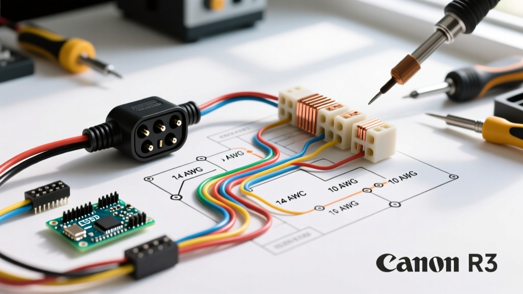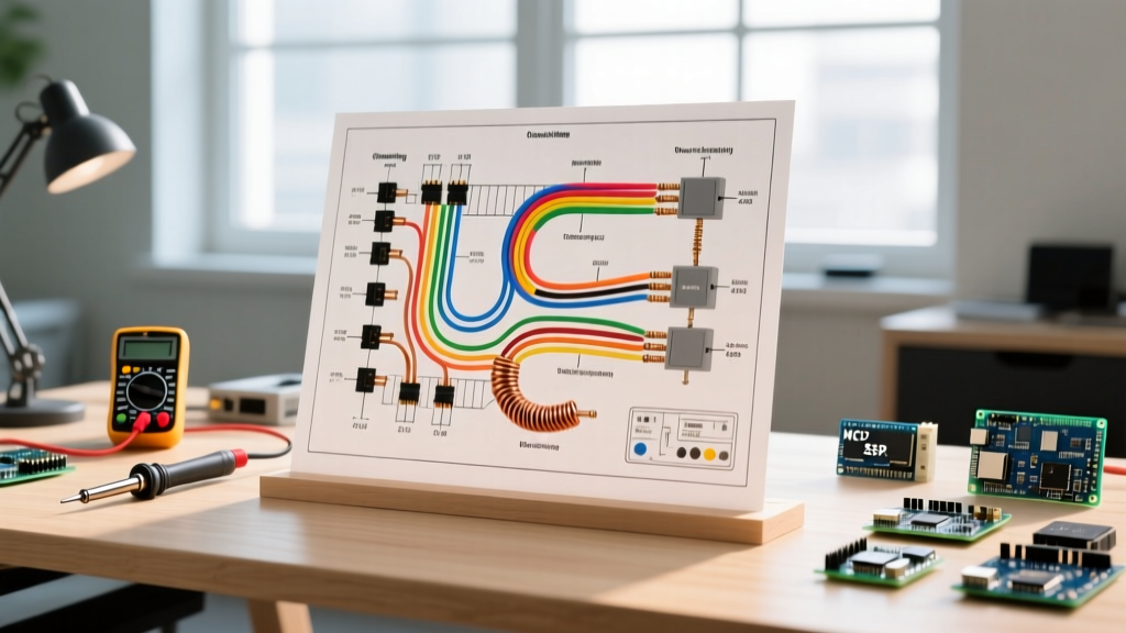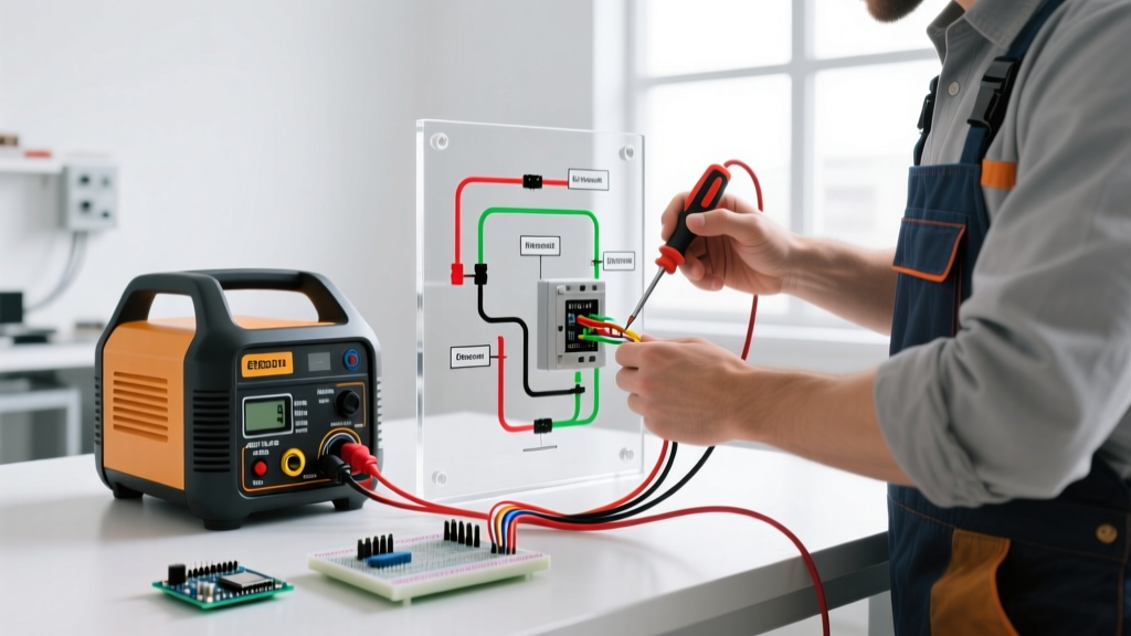

The Core Wiring Diagram: Generator to Transfer Switch to Panel
When wiring generator to electrical panel systems, the only legal and safe method recognized by the National Electrical Code (NEC) involves a manual transfer switch (MTS) or a mechanical interlock kit. The dangerous 'suicide cord' method—backfeeding a 240V dryer or range outlet—is strictly prohibited by code and poses a lethal electrocution risk to utility line workers working on assumed-dead grid lines.
According to the FEMA Ready.gov generator guidelines, portable generators must never be connected directly to house wiring without a proper disconnect mechanism that prevents simultaneous connection to both the utility grid and the generator. The standard wiring diagram for a 30-amp portable generator setup follows a specific 4-wire split-phase topology designed to isolate the utility feed while safely distributing emergency power to critical branch circuits.
Diagram Flow Path & Component Topology
Understanding the physical flow of electricity is critical before terminating any conductors. A standard 120/240V portable generator wiring diagram follows this exact sequence:
- Power Source: Portable Generator (e.g., Westinghouse WGen9500TFc or DuroMax XP12000EH) outputs 120/240V split-phase power via a NEMA L14-30R or L14-50R receptacle.
- Transmission: A heavy-duty NEMA L14-30P to L14-30R twist-lock cord (10 AWG, 4-conductor SOOW cable) bridges the outdoor generator to the home.
- Entry Point: NEMA L14-30R Outdoor Inlet Box (e.g., Leviton 49075 or Bryant 9450FR) mounted on the exterior wall.
- Disconnect/Switching: 30-Amp Manual Transfer Switch (e.g., Reliance Controls 31410CRK or Generac 9854) mounted indoors adjacent to the main panel.
- Destination: Main Electrical Panel (integrating via branch circuit breakers or a main sub-feed lug).
Critical NEC Code Requirements for 2026 Installations
Modern electrical codes have tightened regulations around optional standby systems. When planning your wiring diagram, you must adhere to NEC Article 702 (Optional Standby Systems). Specifically, NEC 702.12 mandates that outdoor generator connection equipment (the inlet box) must be installed in a location that allows for safe cord management, preventing cords from running across walkways or through windows, which compromises the building envelope and creates a fire hazard.
Furthermore, the Electrical Safety Foundation International (ESFI) emphasizes that all transfer equipment must be rated for the maximum fault current available at the service entrance. If your main panel has a 200-amp service with high available fault current, your transfer switch must have an adequate AIC (Amps Interrupting Capacity) rating, typically 10,000 AIC or 22,000 AIC depending on your utility transformer.
Component Sizing and Wire Gauge Matrix
Selecting the correct wire gauge and breaker size is non-negotiable. Undersized conductors will overheat, melt insulation, and cause electrical fires. The table below outlines the standard sizing for copper THHN/THWN-2 conductors routed in PVC or EMT conduit.
| Generator Max Output | Receptacle Type | Transfer Switch Amp Rating | Minimum Copper Wire Gauge | Max Conduit Fill (3/4" EMT) |
|---|---|---|---|---|
| 5,000W - 7,500W | NEMA L14-30 (4-prong) | 30 Amp | 10 AWG | Up to 6 conductors |
| 8,000W - 12,500W | NEMA L14-50 (4-prong) | 50 Amp | 6 AWG | Up to 4 conductors |
| 15,000W+ | NEMA CS6365 / Hardwire | 60 Amp - 100 Amp | 4 AWG to 2 AWG | Consult NEC Chapter 9 |
Note: Always apply the 83% derating factor from NEC 310.15(B)(3)(a) if you have more than three current-carrying conductors in a single conduit run, though standard inlet-to-MTS runs typically only contain four (two hots, one neutral, one ground).
Step-by-Step Wiring Procedure
Step 1: Mount and Wire the Outdoor Inlet Box
Mount the inlet box at least 18 inches above grade to prevent snow or floodwater ingress. Route 10 AWG (or 6 AWG) THHN wires through a 3/4-inch PVC conduit into the interior of the home. Crucial Detail: Do not strip the wire insulation more than 3/4 of an inch. Torque the terminal screws on the inlet box to the manufacturer's specification—typically 45 in-lbs for 10 AWG and 50 in-lbs for 6 AWG copper wire. Loose connections under high continuous load will arc and melt the terminal block.
Step 2: Install the Manual Transfer Switch (MTS)
Mount the MTS directly adjacent to your main electrical panel. You will need to knockout a hole in the side of both panels and install a short nipple conduit to pass the wires. The MTS acts as a sub-panel. The two 'hot' wires from the inlet box connect to the 'Line' terminals on the MTS. The neutral connects to the isolated neutral bus bar inside the MTS, and the ground connects to the equipment grounding bus bar.
Step 3: Branch Circuit Integration
Unlike a whole-house automatic standby generator, a manual transfer switch only powers specific pre-selected circuits (e.g., furnace, well pump, refrigerator, living room outlets). You will remove the hot wire from the selected circuit breaker in the main panel, wire-nut it to the 'Load' wire coming from the MTS, and move the circuit's neutral to the MTS neutral bar. This creates a closed loop that is entirely isolated from the utility grid when the MTS is switched to 'Generator'.
The 'Bonded vs. Floating Neutral' Dilemma
The most common point of failure and confusion when wiring a generator to an electrical panel is managing the neutral-to-ground bond. According to the National Fire Protection Association (NFPA), improper neutral bonding can lead to circulating currents, shocked equipment frames, and nuisance tripping.
- The Problem: Most portable generators under 15kW have a 'bonded neutral' (the neutral and ground are connected at the generator's stator). Your home's main electrical panel also has a bonded neutral. If you connect the two, you create parallel neutral paths. Return current will flow through both the neutral wire and the ground wire, which will instantly trip the GFCI breaker on modern portable generators.
- The Solution: You must use a Switched-Neutral Transfer Switch (like the Reliance Controls X-Series). This specialized MTS physically disconnects the generator's neutral bond from the home's neutral bond when switching power sources, maintaining a single, code-compliant bond point at all times. Alternatively, you can physically remove the neutral bonding strap inside the portable generator (converting it to a 'floating neutral'), but this voids the generator's warranty and makes it unsafe for standalone job-site use.
Troubleshooting Matrix: Common Wiring Failures
| Symptom | Probable Cause | Diagnostic & Fix |
|---|---|---|
| Generator GFCI breaker trips immediately upon plugging in. | Parallel neutral paths (Double bonded neutral). | Verify MTS is a switched-neutral model, or float the generator neutral. |
| 120V appliances work, but 240V appliances (well pump) do not. | One of the 'hot' legs is not making contact at the inlet box. | Check L1 and L2 terminal torque. Test continuity from cord cap to MTS Line lugs. |
| Transfer switch feels hot to the touch after 30 minutes. | Undersized wire gauge or loose terminal connections. | Verify 10 AWG for 30A. Re-torque all lugs to 45 in-lbs. Check for melted insulation. |
| Utility power returns, but MTS won't switch back to 'Line'. | Utility voltage drop or MTS internal relay failure. | Measure voltage at MTS Line terminals. Must be >220V to register utility return. |
Estimated Project Costs & Material Breakdown
Budgeting for a safe, code-compliant generator-to-panel wiring project requires accounting for high-copper-content wiring and specialized switching gear. Below is a realistic 2026 cost estimate for a standard 30-Amp (7,500W) manual transfer switch installation:
- 30A Manual Transfer Switch (10-circuit): $350 - $550
- NEMA L14-30R Outdoor Inlet Box (with flip lid): $60 - $95
- 25ft NEMA L14-30 Generator Cord (10 AWG SOOW): $80 - $130
- Miscellaneous (10 AWG THHN, 3/4" PVC, fittings, wire nuts): $75 - $120
- Professional Electrician Labor (4-6 hours): $600 - $1,100
Total Estimated Cost: $1,165 to $1,995. While DIY installation is possible for experienced hobbyists, the ESFI strongly recommends hiring a licensed electrical contractor to ensure the neutral bonding and fault-current ratings are correctly calculated, protecting both your home and your family from catastrophic electrical failures.
Final Safety Verification
Before starting your generator for the first time after wiring, perform a 'cold test'. With the generator OFF and unplugged, use a multimeter to test for continuity between the inlet box ground terminal and the neutral terminal. There should be infinite resistance (OL). If you read continuity, you have a neutral-to-ground short in your wiring, which must be corrected before applying power. Once verified, start the generator, let it warm up for 3 minutes to stabilize voltage and frequency, and then firmly engage the transfer switch to the 'Generator' position.