
Understanding the Code-Compliant Wiring Diagram for 240 Volt Baseboard Heater
Installing a 240-volt baseboard heater is one of the most efficient ways to add supplemental zone heating to a home, but it requires strict adherence to the National Electrical Code (NEC). Unlike standard 120-volt receptacle circuits, a 240-volt heating circuit carries a significantly higher continuous load, meaning that improper wire sizing, inadequate breaker selection, or poor thermostat placement can lead to catastrophic thermal failures. According to the National Fire Protection Association (NFPA), heating equipment remains a leading cause of residential fire incidents, making code compliance non-negotiable.
In this comprehensive guide, we break down the exact wiring diagram for 240 volt baseboard heater setups, integrating the latest 2026 NEC standards, continuous load calculations, and physical safety clearances. Whether you are wiring a standard 1500W Cadet unit or a high-capacity 2500W Dimplex convector, the electrical topology remains consistent, provided you respect the ampacity limits of your branch circuit.
NEC Article 424: Fixed Electric Space-Heating Equipment
Before pulling any 12/2 NM-B cable, you must understand that baseboard heaters fall under NEC Article 424. This article dictates everything from branch circuit sizing to the physical location of line-voltage thermostats. The most critical takeaway for DIYers and electricians alike is the continuous load rule outlined in NEC 210.20(A).
The 125% Continuous Load Calculation
Baseboard heaters are classified as continuous loads because they are expected to operate at maximum current for three hours or more. Therefore, the branch circuit overcurrent device (breaker) and the wire ampacity must be rated for at least 125% of the heater's maximum wattage.
- Example: A 2000W heater at 240V draws 8.33 Amps (2000 / 240 = 8.33A).
- 125% Rule: 8.33A x 1.25 = 10.41 Amps.
- Result: A 15-Amp breaker and 14 AWG wire are technically sufficient, but industry best practice and many local 2026 amendments mandate a minimum 20-Amp breaker with 12 AWG wire for all 240V dedicated heating circuits to mitigate voltage drop and future-proof the line.
The Core Wiring Topology: Panel to Heater
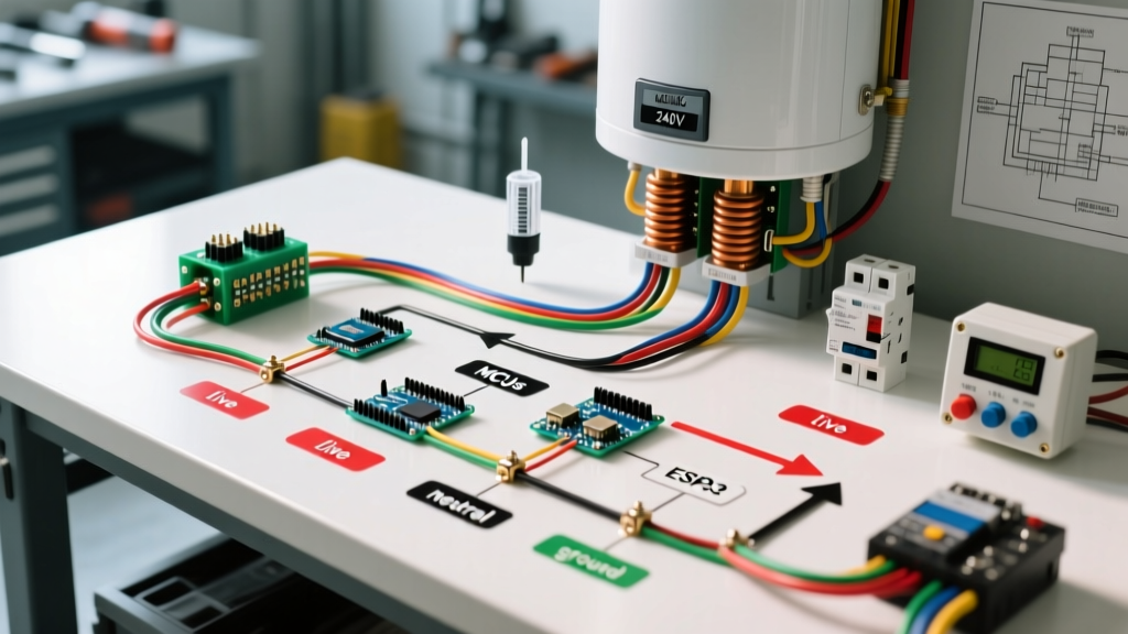
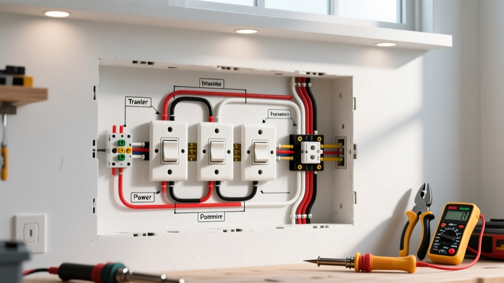
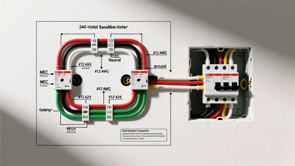
Because we cannot display graphical schematics directly in this text format, below is the precise step-by-step electrical topology that represents the standard wiring diagram for 240 volt baseboard heater configurations featuring an integrated or wall-mounted line-voltage thermostat.
1. The Main Service Panel
Install a 2-pole, 20-Amp breaker (e.g., Square D HOM220CP, retailing around $14 in 2026) into your main load center. Connect the black and white (re-identified with black tape) conductors of your 12/2 NM-B cable to the two breaker terminals. Connect the bare copper ground to the panel's ground bus bar. Note: Never use a tandem or twin breaker; a true 2-pole breaker ensures simultaneous disconnect of both hot legs, which is a strict NEC 424.19 requirement.
2. The Wall-Mounted Line-Voltage Thermostat
Run the 12/2 NM-B cable from the panel to the thermostat junction box. The thermostat acts as the primary switching device.
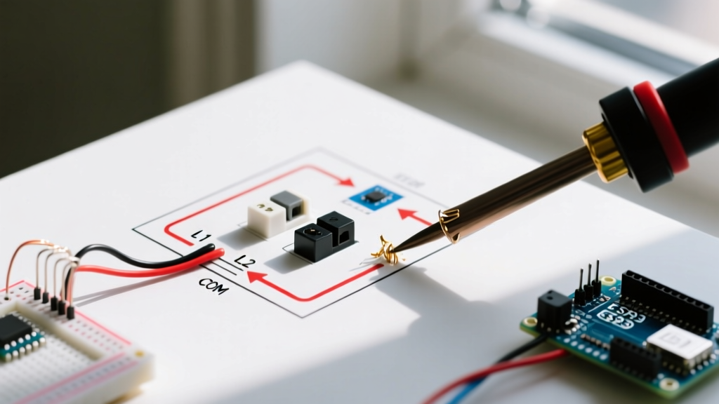
- Line 1 (Black): Connects to the "L1" terminal on the thermostat.
- Line 2 (White with Black Tape): Connects to the "L2" terminal on the thermostat.
- Ground: Pigtailed to the metal junction box and the thermostat's green grounding screw.
3. The Thermostat to the Heater
Run a second piece of 12/2 NM-B from the thermostat to the heater's built-in junction box.
- Load 1 (Black): Connects from the thermostat's "T1" terminal to one of the heater's element wires (heaters are non-polarized, so either element wire works).
- Load 2 (White with Black Tape): Connects from the thermostat's "T2" terminal to the heater's remaining element wire.
- Ground: Pigtailed to the heater's metal chassis grounding screw.
Safety Warning: Never switch only one leg of a 240V circuit. While the heater will turn off, the internal elements will remain energized at 120V to ground, posing a lethal shock hazard during maintenance. Always use a double-pole thermostat or a smart thermostat specifically rated for 240V double-pole switching, such as the Mysa Smart Thermostat v3.
Wire Sizing and Breaker Matrix
Selecting the correct wire gauge is paramount. The following table outlines the maximum allowable wattages for standard residential 240V baseboard heaters based on the 125% continuous load rule.
| Breaker Size (2-Pole) | Wire Gauge (NM-B) | Max Continuous Wattage (240V) | NEC Reference |
|---|---|---|---|
| 15 Amp | 14 AWG | 2,880 Watts | 210.20(A) / 240.4(D) |
| 20 Amp | 12 AWG | 3,840 Watts | 210.20(A) / 240.4(D) |
| 30 Amp | 10 AWG | 5,760 Watts | 210.20(A) / 240.4(D) |
Pricing Note: As of early 2026, a 250-foot roll of 12/2 NM-B Romex averages $165-$185, translating to roughly $0.70 per foot. Always buy 15% more than your measured run to account for junction box loops and errors.
Physical Clearances and Installation Safety
The wiring diagram is only half the battle; physical placement dictates operational safety. The U.S. Department of Energy emphasizes that improper clearance restricts convection airflow, causing the heater's internal thermal limit switch to trip repeatedly or, worse, igniting nearby combustibles.
Mandatory NEC Clearances
- Receptacle Outlets (NEC 424.13): Baseboard heaters must not be installed directly beneath a receptacle outlet. Furthermore, there must be a minimum horizontal clearance of 12 inches between the heater and any adjacent receptacle. This prevents power cords from draping over the hot fins.
- Flooring Clearance: Maintain at least a 1/2-inch gap between the bottom of the heater and the finished floor (carpet or hardwood) to allow cold air intake. Most manufacturers, like Cadet and Dimplex, include built-in spacer legs for this exact purpose.
- Curtains and Combustibles: Maintain a minimum 12-inch clearance from drapes, furniture, and bedding on all sides, particularly the top discharge grille where air temperatures can exceed 150°F (65°C).
Upgrading to Smart Line-Voltage Thermostats
In 2026, traditional mechanical bimetallic thermostats (like the Honeywell CT410A) are increasingly being replaced by Wi-Fi-enabled line-voltage smart thermostats. These devices offer superior energy savings by utilizing geofencing and algorithmic learning to reduce phantom heating.
When wiring a smart thermostat like the Mysa v3 for Baseboard Heaters, the physical wiring diagram remains identical to the mechanical version (L1, L2, T1, T2). However, smart thermostats require a stable Wi-Fi connection and often draw a tiny amount of standby current. Ensure your chosen smart thermostat is explicitly rated for the amperage of your circuit. The Mysa v3 is rated for 16 Amps (3840W at 240V), meaning it can safely control a 20-Amp circuit loaded up to its continuous maximum. If your heater exceeds 3840W, you must use a heavy-duty contactor relay, triggered by the smart thermostat, to handle the primary load.
Common Failure Modes and Troubleshooting
Even with a perfect wiring diagram for 240 volt baseboard heater systems, environmental factors and component degradation can cause issues. Here is how to diagnose the most common field failures:
1. The Breaker Trips After 20 Minutes
Diagnosis: This is a classic thermal trip, not a short circuit. It indicates the circuit is overloaded beyond the breaker's continuous rating, or the breaker itself has weakened from years of thermal cycling. Verify the total wattage of all heaters on the circuit. If you have two 1500W heaters on a single 20A breaker (Total 3000W), you are exceeding the 3840W absolute max, but if the voltage drops to 230V during winter peaks, amperage spikes. Fix: Separate the heaters onto independent 20A circuits.
2. Heater Emits a "Clicking" Sound and Won't Turn On
Diagnosis: The internal thermal limit switch has tripped due to restricted airflow. According to Cadet Manufacturing Safety Guidelines, this is almost always caused by dust buildup on the heating element or a piece of furniture blocking the top grille. Fix: Turn off the 2-pole breaker, remove the front cover, and vacuum the aluminum fins. Ensure the manual reset button on the limit switch (located inside the junction box) is fully depressed.
3. Thermostat Feels Warm to the Touch
Diagnosis: Line-voltage thermostats handle the full current of the heating element. If the wire connections at the thermostat's L1/L2 terminals are loose, they will create high resistance, generating localized heat that bleeds into the plastic faceplate. Fix: This is a severe fire hazard. Turn off the power, cut back the oxidized wire ends, strip fresh copper, and secure them using wire nuts rated for high-temperature environments (such as Ideal WingNut 341).
Frequently Asked Questions
Can I use 14/2 wire for a 240V baseboard heater?
While NEC 240.4(D) allows 14 AWG on a 15A breaker, most modern local jurisdictions and electrical inspectors require a minimum of 12 AWG wire on a 20A breaker for all 240V space heating circuits to ensure mechanical durability and reduce voltage drop over long runs.
Do I need a GFCI breaker for a baseboard heater?
No. NEC Article 424 does not require Ground Fault Circuit Interrupter (GFCI) protection for fixed, hardwired baseboard heaters unless they are located in a bathroom (which is highly discouraged and often prohibited by local codes due to towel-clearance issues). Standard thermal-magnetic breakers are the correct choice.
Does the white wire need to be marked in a 240V circuit?
Yes. NEC 200.7(C) mandates that if a white or gray wire is used as an ungrounded (hot) conductor in a 240V cable assembly, it must be permanently re-identified with black or red electrical tape, or paint, at every point where the conductor is visible and accessible.