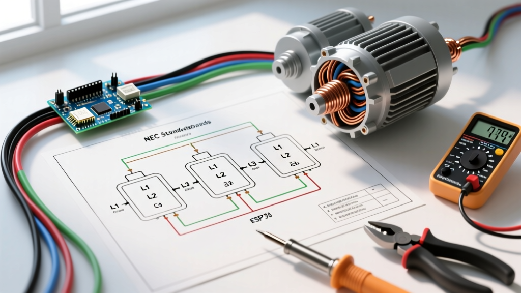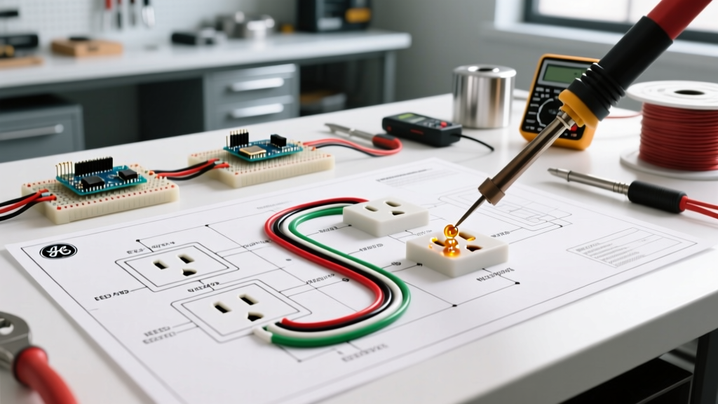

The Terminology Trap: "Two-Way" vs. "3-Way" Switches
Before pulling any wire, we must address a critical semantic divergence that causes dangerous wiring errors. If you are searching for a wiring diagram for a two-way switch, you are likely referencing the UK, Australian, or European terminology (BS 7671 / AS/NZS 3000) for a switch that controls a single light fixture from two separate locations. In the United States, under the National Electrical Code (NEC), this exact same configuration is universally known as a 3-way switch.
Conversely, what North Americans call a "single-pole" switch (controlling a light from one location) is referred to as a "1-way" switch in the UK. Attempting to wire a North American 3-way circuit using international 2-way diagrams without adapting for NEC color codes and grounding requirements is a primary cause of residential electrical fires and failed inspections. This guide bridges that gap, providing a code-compliant, safety-first wiring diagram for a two-way switch (US 3-way equivalent) based on the latest 2026 NEC standards.
⚠️ SAFETY CALLOUT: Never rely solely on wire color. Previous homeowners or unlicensed handymen often miswire traveler and line/load conductors. Always verify dead circuits using a CAT III or CAT IV rated multimeter, such as the Fluke 117 True-RMS Digital Multimeter, before touching any terminal screws.Core NEC Code Mandates for Multi-Location Switching
When executing your wiring diagram for a two-way switch, strict adherence to NEC Article 404 (Switches) is non-negotiable. Modern code updates have fundamentally changed how these circuits must be roughed in, particularly regarding neutral wires and equipment grounding.
1. The Neutral Conductor Requirement (NEC 404.2(C))
"For new construction, a grounded (neutral) conductor must be provided at every switch location controlling lighting loads." — NEC Article 404.2(C)
Historically, electricians ran a 14/2 or 12/2 cable between the two switch locations, using the white wire as a traveler and re-identifying it with black tape. This is now a severe code violation in most jurisdictions. Because modern smart switches (like the Lutron Caseta or Leviton Decora Smart) require a neutral wire to power their internal Wi-Fi/Zigbee radios, the NEC now mandates that a dedicated neutral be present at both switch boxes. You must use 14/3 or 12/3 NM-B (Romex) cable between the switch locations to accommodate the Line, Load, two Travelers, and the Neutral.
2. Equipment Grounding (NEC 404.9(B))
Every switch yoke must be bonded to the equipment grounding conductor (EGC). If you are retrofitting an older home with ungrounded 2-wire cloth-sheathed cable, you cannot simply install a modern 3-way switch and leave the ground screw empty. You must either run a new grounded cable or install a GFCI breaker at the panel and label the switch plate "No Equipment Ground" per NEC 406.4(D)(4). For full compliance and safety, pulling new 14/3 NM-B grounded cable is the only recommended path in 2026.
Bill of Materials & Component Specifications
To ensure your wiring diagram for a two-way switch translates into a safe, physical installation, use components rated for your specific circuit amperage. Do not mix 15A and 20A hardware.
| Component | 15-Amp Circuit Spec | 20-Amp Circuit Spec | Estimated 2026 Cost |
|---|---|---|---|
| Circuit Breaker | 15A Single-Pole (e.g., Eaton BR115) | 20A Single-Pole (e.g., Eaton BR120) | $6.50 - $9.00 |
| NM-B Cable (Line/Load) | 14/2 NM-B with Ground (Southwire) | 12/2 NM-B with Ground (Southwire) | $0.45 - $0.75 / ft |
| NM-B Cable (Travelers) | 14/3 NM-B with Ground (Southwire) | 12/3 NM-B with Ground (Southwire) | $0.85 - $1.20 / ft |
| Switch Hardware | 15A 3-Way Toggle (Leviton 5603-2W) | 20A 3-Way Toggle (Leviton 5623-2W) | $4.00 - $7.50 each |
| Wire Connectors | Ideal WingNut 341 (Tan/Red) | Ideal WingNut 342 (Red/Yellow) | $0.15 each |
Step-by-Step Wiring Diagram Execution
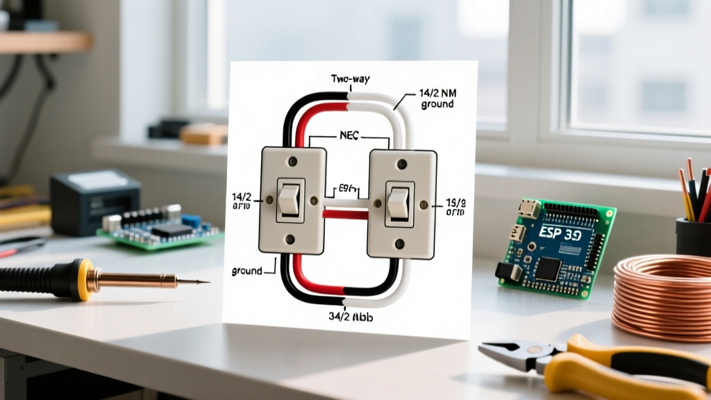
The most common and code-compliant topology for a two-way (3-way) switch circuit is the Line-to-Switch 1, Switch 1-to-Switch 2, Switch 2-to-Load configuration. Below is the exact terminal mapping.
Step 1: The Line Box (Switch 1)
- Power Feed: The 14/2 NM-B power cable from the breaker panel enters this box. Connect the bare copper ground to the box grounding pigtail and the switch's green ground screw.
- Neutral Splice: Connect the white neutral wire from the panel to the white neutral wire of the 14/3 traveler cable using a WAGO 221 lever-nut or Ideal WireNut. Do not connect the neutral to the standard toggle switch.
- Line Hot: Connect the black hot wire from the panel to the Common Terminal (usually the dark-colored or black-brass screw) on Switch 1.
- Travelers: Connect the black and red wires of the 14/3 traveler cable to the two Brass Terminal Screws on Switch 1. Polarity between these two does not matter.
Step 2: The Load Box (Switch 2)
- Light Fixture Feed: The 14/2 NM-B cable running up to the light fixture enters this box. Connect bare grounds together and pigtail to Switch 2's ground screw.
- Neutral Splice: Connect the white neutral from the 14/3 traveler cable directly to the white neutral going up to the light fixture.
- Travelers: Connect the black and red wires from the 14/3 traveler cable to the two Brass Terminal Screws on Switch 2.
- Load Hot: Connect the black wire from the 14/3 traveler cable (which is acting as the switched hot returning from Switch 1) to the black wire going up to the light fixture. Wait, correction for standard topology: The black wire of the 14/3 connects to the Common Terminal (dark screw) on Switch 2. The black wire going up to the light fixture (Load) also connects to this same Common Terminal using a pigtail, or if using a 14/2 to the light, the black of the 14/3 and the black of the 14/2 are spliced and pigtailed to the Common screw.
Upgrading to Smart Switches: Code & Compatibility
If your wiring diagram for a two-way switch is intended for a smart home upgrade, standard mechanical 3-way switches are replaced by smart relays. The Consumer Product Safety Commission (CPSC) emphasizes that smart switches must be installed strictly according to manufacturer listings to prevent overheating and fire hazards.
Lutron Caseta vs. Leviton Decora Smart
- Lutron Caseta (PD-5S-DV): Requires a neutral wire. In a 3-way setup, you install the smart switch at the Line box, cap the travelers together at the Load box (creating a single-pole circuit), and use a Pico remote mounted to the wall plate at the second location. This bypasses the need for complex traveler wiring but requires the neutral at the primary box.
- Leviton Decora Smart (D23SR-2RW): Leviton's 2026 Wi-Fi Matter-enabled 3-way switches require you to wire both the primary and the companion switch into the traveler circuit. Both boxes must have a neutral wire present. This maintains physical hardwired control at both locations without relying on battery-powered remotes.
Critical Failure Modes & Troubleshooting
Even with a perfect wiring diagram for a two-way switch, field conditions introduce variables. Here is how to diagnose the three most common code violations and failures:
1. The "Switched Neutral" Violation
Symptom: The light turns on and off correctly, but the light socket remains energized with 120V even when the switch is in the OFF position. Changing a bulb poses a severe shock hazard.
Cause: The installer routed the constant hot directly to the light fixture and used the switch to break the neutral return path.
Fix: This is a direct violation of NEC Article 404.2(B), which mandates that switches must only open the ungrounded (hot) conductor. You must re-pull the cables to ensure the switch interrupts the black hot wire, not the white neutral.
2. Traveler Cross-Wiring
Symptom: Switch A turns the light on, but Switch B will only turn it off if Switch A is in a specific position. The switches do not operate independently.
Cause: One of the traveler wires is incorrectly landed on the Common (dark) terminal screw.
Fix: Use your multimeter's continuity setting. With the power OFF, identify the Common screw on the switch body (it is usually isolated from the brass pair). Ensure the Line/Load hot is on the Common, and the two runners are strictly on the brass traveler screws.
3. Bootleg Grounds on Metal Faceplates
Symptom: A non-contact voltage tester (NCVT) alarms when brought near the metal switch plate screws.
Cause: Inductive coupling from the hot travelers, combined with an ungrounded metal yoke or faceplate.
Fix: Ensure the bare copper EGC is pigtailed to both the metal junction box (if metal) and the green grounding screw on the switch yoke. Per NEC 404.9(B), the faceplate must be grounded. If the grounding path is broken, replace metal plates with UL-listed non-conductive polycarbonate plates.
Frequently Asked Questions
Can I use 14/2 wire between the two switches?
No. Using 14/2 wire between two 3-way switches forces you to use the white wire as a hot traveler. While older codes allowed this if re-identified with black tape, the modern NEC 404.2(C) requires a dedicated neutral at the switch box for future smart-switch compatibility. You must use 14/3 (or 12/3 for 20A circuits) to carry the two travelers and the neutral safely.
Does it matter which traveler wire goes to which brass screw?
No. The two brass screws on a standard 3-way switch are internally connected to a common toggle mechanism. Swapping the red and black traveler wires between the brass screws will not affect the operation of the circuit or violate any electrical codes.
What is the maximum load for a standard residential two-way switch?
Standard residential toggle switches (like the Leviton 5603) are rated for 15 Amps at 120V AC, equating to a maximum resistive load of 1,800 Watts. However, for inductive loads like large LED drivers or fluorescent ballasts, you must derate the switch or use a heavy-duty 20A commercial-grade switch to prevent contact pitting and premature failure.