
The Definitive 7-Way Wiring Diagram for Electric Brakes
When towing a trailer with a Gross Vehicle Weight Rating (GVWR) over 3,000 lbs, electric brakes are not just a recommendation; they are a legal requirement in most jurisdictions. According to the NHTSA trailer towing safety guidelines, a properly synchronized braking system is critical for maintaining vehicle stability and preventing jackknife incidents. However, the most common point of failure in any towing setup is the electrical harness. This comprehensive wiring diagram electric brakes guide breaks down the 7-way RV blade connector, brake controller integration, and the exact wire gauges required for safe, reliable operation in 2026.
Safety Warning: Always disconnect the tow vehicle's battery and the trailer's breakaway battery before splicing, stripping, or terminating any wires in the braking circuit. A short circuit on the 12V auxiliary or brake line can instantly fry a $150+ proportional brake controller.
Standard 7-Way RV Blade Connector Pinout
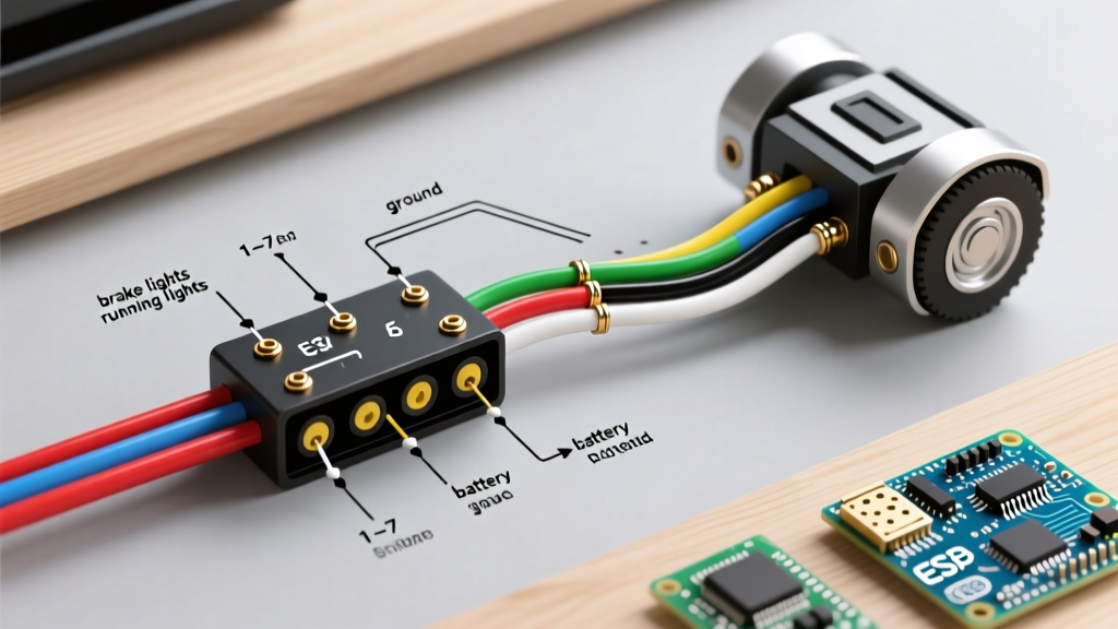
The 7-way RV blade (SAE J286 standard) is the universal connector for modern trailers equipped with electric brakes. Below is the exact pinout reference you need when looking at the vehicle-side socket (pins facing you) or the trailer-side plug (pins facing away).
| Pin Position | Wire Color | Function | Recommended Gauge |
|---|---|---|---|
| 1 (Top Center) | White | Ground (GD) | 8 AWG or 10 AWG |
| 2 (Top Right) | Blue | Electric Brakes (EC) | 10 AWG |
| 3 (Bottom Right) | Green | Tail / Running Lights (TM) | 12 AWG |
| 4 (Center Right) | Black | 12V Auxiliary Power (+12V) | 10 AWG |
| 5 (Bottom Left) | Red | Left Turn / Stop (LT) | 12 AWG |
| 6 (Top Left) | Brown | Right Turn / Stop (RT) | 12 AWG |
| 7 (Center Left) | Yellow | Reverse Lights / Aux (RE) | 12 AWG |
Pro Tip: The white ground wire is the most critical wire in the entire harness. As of 2026, advanced proportional controllers rely on high-frequency PWM (Pulse Width Modulation) signals. A weak ground causes voltage spikes that will force the controller's microprocessor into a continuous reset loop.
Brake Controller Integration: Wiring the Cabin
The trailer's blue brake wire must connect to the blue output wire of your in-cabin brake controller. Let us look at the wiring requirements for the two most dominant controllers on the market today.
1. Tekonsha Prodigy P3 (Model 90195)
The Prodigy P3 remains a staple due to its robust internal inertia sensor. It utilizes a simple 4-wire pigtail:
- White: Ground to vehicle chassis (use a dedicated ring terminal, do not daisy-chain).
- Black: 12V constant power from the battery via a 30-amp inline circuit breaker.
- Blue: Output to the 7-way connector (Pin 2).
- Red: Stoplight switch input (connects to the cold side of the vehicle's brake pedal switch).
2. Redarc Tow-Pro Elite V3
The Redarc V3 uses active calibration and requires a highly stable DC ground. It features a 6-pin harness. Unlike the Tekonsha, the Redarc requires an ignition-switched 12V source on its red wire to wake the unit, while the yellow wire handles the stoplight trigger. Refer to the etrailer wiring database for vehicle-specific stoplight switch tap locations, as modern CAN-bus systems often require a dedicated relay module rather than a direct splice.
Wire Gauge Selection & Voltage Drop Calculations
Using the wrong wire gauge for the electric brake circuit is a leading cause of weak braking performance. Electric brake magnets draw significant current. A standard 10-inch brake magnet draws roughly 3.2 amps, while a 12-inch magnet draws up to 4.0 amps at 12V DC.
If you are wiring a dual-axle trailer (4 brakes), your total maximum draw is approximately 16 amps. Let us calculate the voltage drop over a standard 25-foot trailer (50 feet of total wire length including the ground return):
- Using 12 AWG Wire: Resistance is ~1.588 ohms per 1,000 ft. For 50 ft, resistance is 0.0794 ohms. At 16 amps, the voltage drop is 1.27V. The magnets only receive 10.73V, reducing braking torque by up to 15%.
- Using 10 AWG Wire: Resistance is ~0.998 ohms per 1,000 ft. For 50 ft, resistance is 0.0499 ohms. At 16 amps, the voltage drop is 0.79V. The magnets receive 11.21V, ensuring maximum clamping force.
Verdict: Always use 10 AWG stranded copper for the blue electric brake wire and the white ground wire on dual-axle trailers. For single-axle trailers, 12 AWG is acceptable, but 10 AWG is highly recommended for future-proofing.
The Breakaway Switch Circuit: Your Last Line of Defense
The breakaway switch is designed to apply full battery power to the trailer brakes if the trailer separates from the tow vehicle. It must be wired in parallel with the brake controller's output.
- Power Source: Connect the positive terminal of the breakaway battery (typically a 12V 5Ah Sealed Lead Acid battery) to one terminal of the breakaway switch.
- Output Splice: Connect the second terminal of the breakaway switch to the Blue electric brake wire. This splice should occur between the 7-way plug and the trailer's axle wiring harness.
- Grounding: Connect the negative terminal of the breakaway battery directly to the trailer frame using an 8 AWG white wire and a star washer to bite through the paint.
- Charging Line: If your breakaway kit includes a charging relay, connect it to the Black 12V auxiliary pin (Pin 4) on the 7-way plug to keep the battery topped off while driving.
Multimeter Troubleshooting: Diagnosing Brake Faults
When your brake controller displays an 'S.H.' (Short Circuit) or 'O.L.' (Open Load) error code, do not guess. Use a digital multimeter (like a Fluke 87V) to isolate the fault. Consult Tekonsha official installation resources for controller-specific error definitions, but follow this universal diagnostic flow:
Step 1: Test the Magnets (Open Load Diagnosis)
Disconnect the trailer from the truck. Set your multimeter to Ohms (Ω). Place the probes on the blue and white wires at the trailer's 7-way plug.
- Single Axle (2 brakes): Expected reading is 1.5 to 2.0 Ω.
- Dual Axle (4 brakes): Expected reading is 0.75 to 1.0 Ω.
- Reading 'OL' (Infinite): You have a severed blue wire, a corroded butt splice, or a burnt-out magnet coil.
Step 2: Test for Shorts (Short Circuit Diagnosis)
Keep the multimeter on Ohms. Place one probe on the blue brake wire and the other on the bare trailer frame.
- Expected reading: 'OL' (Infinite). There should be zero continuity to ground.
- Reading near 0 Ω: The blue wire is pinched against the chassis, or a brake magnet has internally shorted to its mounting bracket. Inspect the wire routing near the axle leaf springs, where vibration frequently wears through wire loom.
Termination Best Practices for 2026
The environment under a trailer is brutal. Moisture, road salt, and extreme vibration will destroy poor connections in a single season. Abandon standard vinyl crimp caps. Instead, use adhesive-lined heat shrink butt connectors. When crimped and heated, the internal thermoplastic adhesive melts and seals the wire strands, creating a completely waterproof, strain-relieved bond. Finally, pack all 7-way plug terminals with a high-quality dielectric grease (such as Permatex 22058) to prevent copper oxidation and galvanic corrosion between the brass pins and the socket contacts.