
Understanding the 3-Wire Christmas Light Architecture
When DIYers and professional holiday installers search for a wiring diagram for 3 wire Christmas lights, they are typically dealing with one of two distinct electrical architectures. Standard residential mini-lights use a simple 2-wire series/parallel circuit. However, 3-wire harnesses are the industry standard for commercial-grade LED strings (which utilize dual-return circuits for alternating colors or chasing effects) and addressable RGB pixel nodes (which require a dedicated data line). Misidentifying these harnesses is the leading cause of blown rectifiers and dead pixels during mid-season repairs.
⚠️ High-Voltage Safety Warning: Commercial 3-wire LED strings do not use step-down transformers. The inline full-wave rectifier converts 120V AC directly to ~170V DC peak. Always unplug the string and discharge the capacitors before cutting or splicing the 3-wire harness. For comprehensive safety protocols, always refer to the Electrical Safety Foundation International (ESFI) holiday lighting guidelines.
Scenario A: Commercial LED Strings (Common Hot + Dual Returns)
Commercial C9/C7 retrofit strings and high-end roofline mini-lights often feature a 3-wire extruded PVC harness. This design allows manufacturers to wire two separate LED circuits (e.g., Warm White and Cool White, or Red and Green) that share a common positive voltage but have independent negative return paths. This enables alternating flash patterns using a simple 2-channel plug controller without needing expensive microchips in every bulb.
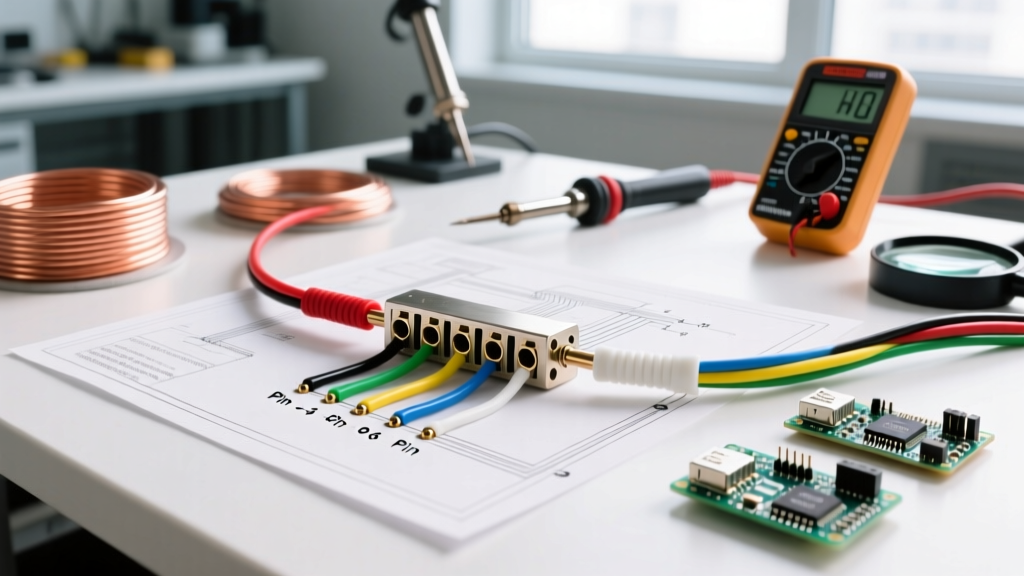
The 3-Wire Commercial Pinout & Wiring Diagram
| Wire Position | Standard Color Code | Electrical Function | Multimeter Reading (vs. Ground) |
|---|---|---|---|
| Wire 1 (Outer) | White or Ribbed | Common DC+ (from Rectifier) | +165V to +170V DC Peak |
| Wire 2 (Center) | Green or Solid | DC- Return (Circuit A / Color 1) | 0V (Switched by controller) |
| Wire 3 (Outer) | Brown or Striped | DC- Return (Circuit B / Color 2) | 0V (Switched by controller) |
Failure Mode: The "Half-Dark" String
If you plug in a commercial 3-wire string and only one color illuminates (or only half the physical bulbs light up), you have a severed return wire. Because Wire 1 (Common Hot) is intact, the circuit with the unbroken return path will function perfectly. To fix this, you must trace the harness with a True-RMS multimeter set to continuity mode, find the break, and splice the specific return wire.
Scenario B: Addressable RGB Pixel Nodes (WS2811 / WS2815)
In the realm of custom holiday lighting, 3-wire harnesses are synonymous with addressable RGB pixels. Unlike commercial strings, these operate on low-voltage DC (5V or 12V) and require a microcontroller (like a Falcon F48 or ESP32) to send data packets to each individual node.
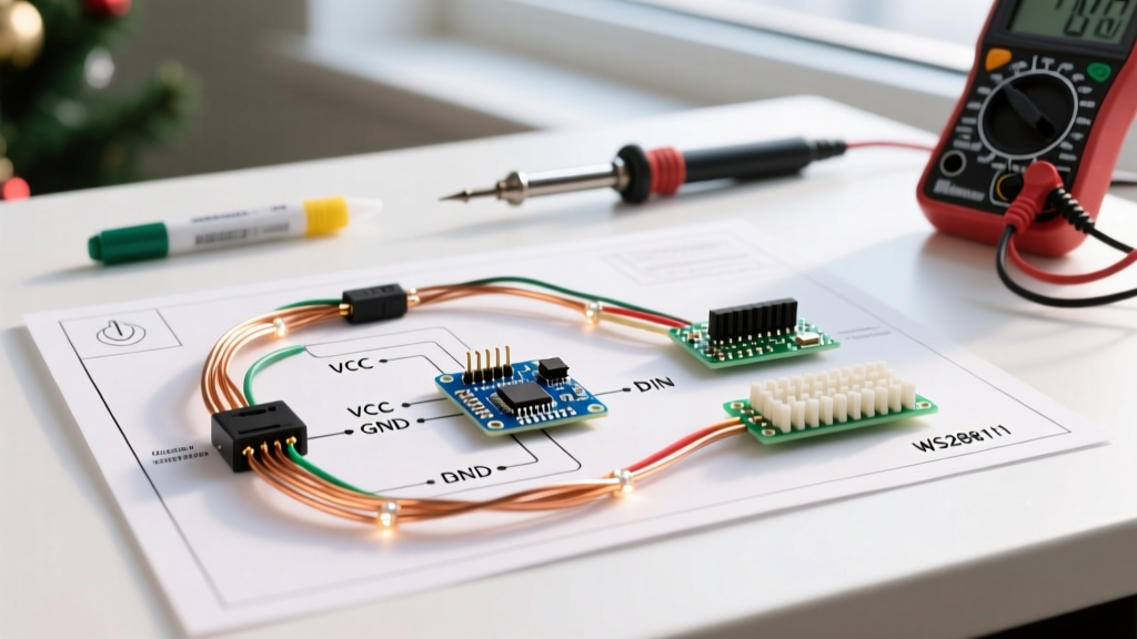
Addressable 3-Wire Data Injection Diagram
- Wire 1 (Red): VCC (12V DC+ or 5V DC+)
- Wire 2 (White/Green): DATA (5V logic level PWM signal)
- Wire 3 (Black/White): GND (DC- Return)
For deep technical specifications on timing and data injection for these 3-wire nodes, the Adafruit NeoPixel UberGuide remains the definitive engineering reference for signal degradation and wire gauge requirements.
Crucial Rule: The Data Line Null Node
When wiring 12V WS2811 3-wire pixels, the first pixel in the chain acts as a "null" or sacrificial node. The data signal from your controller must pass through the first pixel's internal IC to be re-timed and amplified for the rest of the string. Never bypass the first pixel when extending a 3-wire addressable run, or you will experience severe data flickering on the subsequent nodes.
Step-by-Step Repair Guide for Cut 3-Wire Harnesses
Repairing a 3-wire commercial harness requires more than just twisting wires together. The high DC voltage demands robust, weatherproof insulation to prevent arcing and GFCI trips.
- Isolate and Strip: Cut away the damaged section of the 3-wire PVC jacket. Strip exactly 1/4 inch of insulation from each of the three internal copper conductors (typically 22 AWG stranded).
- Stagger the Splices: Cut Wire 2 and Wire 3 at slightly different lengths so that the eventual solder joints do not sit directly parallel to one another. This prevents short circuits if the insulation fails.
- Solder and Seal: Tin the wires with rosin-core solder. Use a 60W+ soldering iron to ensure a quick, shiny joint. Slide 3:1 adhesive-lined polyolefin heat shrink (3/32" diameter) over each joint. Apply heat until the adhesive oozes from the ends, creating a waterproof seal.
- Outer Jacket Recovery: Wrap the entire repaired section in self-amalgamating silicone tape, followed by a larger piece of 1/2" heat shrink to mimic the original extruded PVC jacket profile.
Wire Gauge Sizing for 3-Wire Extensions
When extending 3-wire addressable pixel runs, voltage drop on the VCC and GND lines is the primary enemy. The Data wire carries virtually zero amperage, but the power wires must handle the cumulative load of the pixels.
| Pixel Type | Max Amps per 50 Nodes | Recommended VCC/GND Wire Gauge | Max Run Before Power Injection |
|---|---|---|---|
| 5V WS2811 (12mm) | ~3.0A (White full on) | 16 AWG Stranded Copper | 50 Pixels (16.4 ft) |
| 12V WS2811 (Bullet) | ~1.25A (White full on) | 18 AWG Stranded Copper | 150 Pixels (49.2 ft) |
| 12V WS2815 (Backup Data) | ~1.25A (White full on) | 18 AWG Stranded Copper | 150 Pixels (49.2 ft) |
Troubleshooting Matrix: 3-Wire Christmas Lights
Use this diagnostic matrix to quickly identify faults in both commercial and addressable 3-wire systems.
| Symptom | System Type | Probable Cause | Expert Fix |
|---|---|---|---|
| Only one color illuminates | Commercial LED | Severed Wire 2 or Wire 3 (Return) | Splice broken return wire; check plug controller pins. |
| Entire string dead, plug fuse intact | Commercial LED | Blown Full-Wave Bridge Rectifier | Replace inline rectifier (e.g., MB6S or KBP206). |
| Random color flickering mid-run | Addressable RGB | Data signal degradation / Voltage drop | Inject 12V power at the fault location; check Data wire continuity. |
| First 10 pixels work, rest are dead | Addressable RGB | Broken Data line after 10th node | Resolder the White/Green Data wire on the output of the 10th pixel. |
Final Expert Advice on GFCI Nuisance Tripping
When repairing 3-wire commercial strings, moisture ingress at the splice point is the #1 cause of GFCI nuisance tripping. Standard electrical tape is porous and will absorb humidity over a few weeks outdoors. Always use dual-wall, adhesive-lined heat shrink. The inner layer of hot-melt adhesive bonds to the copper and PVC jacket, displacing moisture and creating a permanent, IP67-rated environmental seal that will survive harsh winter conditions.