
Repurposing the SBC 350: The Standalone 'Appliance' Configuration
When adapting a Small Block Chevrolet (SBC) 350 V8 engine to serve as a stationary prime mover for industrial appliances—such as PTO-driven generators, commercial irrigation pumps, or stationary sawmills—you are effectively treating the engine as a heavy-duty appliance. Stripping away the vehicle chassis means losing the factory fuse block, ignition switch, and ECU. To ensure reliable, code-compliant operation in 2026 and beyond, you must master the standalone wiring diagram for Chevy 350 configurations.
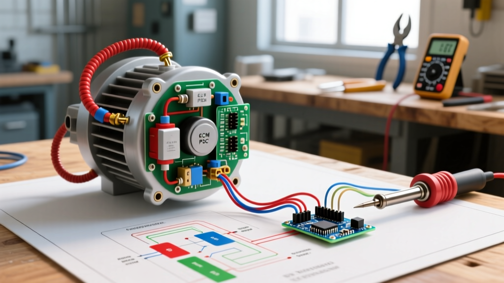
Unlike automotive applications where the alternator communicates with a dashboard ammeter and the ignition is tied to a steering column switch, a standalone Chevy 350 requires a simplified, ruggedized 12V DC architecture. This tutorial breaks down the exact wiring topology required to integrate a GM HEI (High Energy Ignition) distributor, a Delco-style alternator, and a gear-reduction starter into a cohesive industrial power plant.
⚠️ Critical Warning: The Factory Ballast ResistorIf your Chevy 350 was originally equipped with a points-style ignition, the factory wiring harness utilizes a resistance wire that drops voltage to 9V during normal running conditions. The GM HEI distributor requires a full, unresisted 12V to function. Never reuse the factory points resistance wire for an HEI swap, or the 4-pin module will starve for voltage, causing severe misfires under load and eventual module failure.
Phase 1: HEI Ignition Circuit Architecture
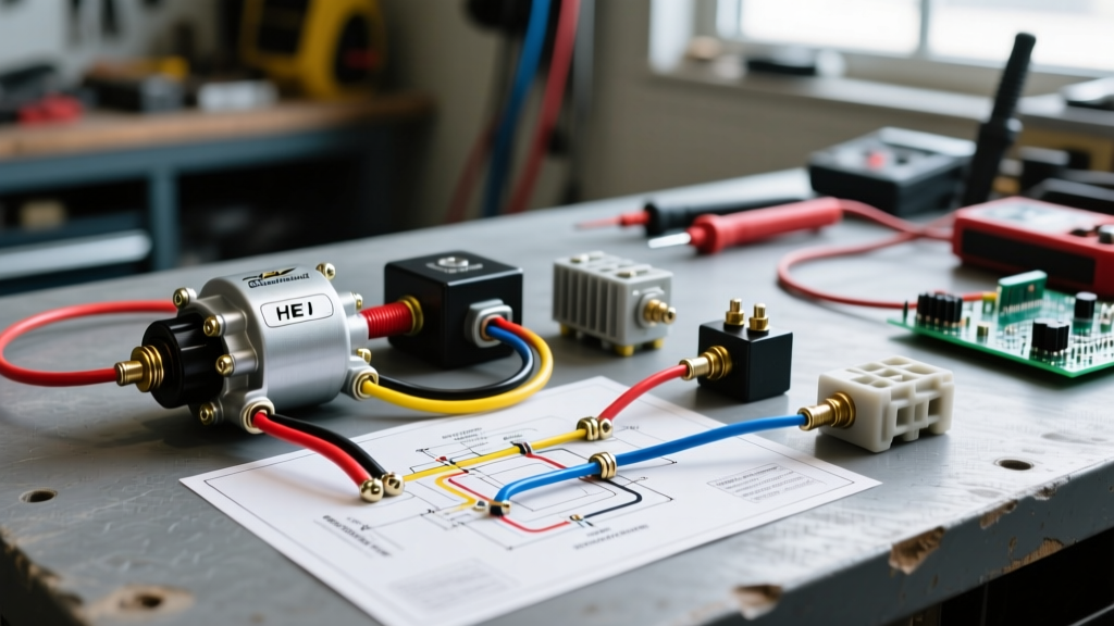
The GM HEI distributor is the gold standard for standalone SBC 350 applications due to its self-contained coil and solid-state 4-pin control module (commonly replaced by the AC Delco D1321C or equivalent). Wiring the HEI requires only three primary connections, but the execution is where most industrial setups fail.
Step-by-Step HEI Wiring
- Switched 12V Feed (BATT Terminal): Run a dedicated 12 AWG SXL (cross-linked polyethylene) wire from your main battery positive busbar, through a heavy-duty 30A marine-grade toggle switch (acting as your ignition/run switch), directly to the 'BATT' terminal on the HEI cap. SXL wire is rated for 125°C, which is mandatory for the high-ambient heat of stationary engine enclosures.
- Tachometer Output: The 'TACH' terminal on the HEI cap outputs a 12V square wave pulse. If your industrial appliance utilizes a digital RPM safety governor or a diagnostic hour-meter, connect this terminal to the tach signal input using 18 AWG shielded wire to prevent electromagnetic interference (EMI) from the high-voltage spark plug wires.
- Distributor Grounding: The 4-pin module completes its circuit through the physical body of the distributor. You must ensure the distributor housing is perfectly clean where it mates to the cast-iron or aluminum intake manifold. Apply a thin layer of dielectric grease to prevent galvanic corrosion, which can cause the module to lose its ground path mid-operation.
For a comprehensive look at the internal pinout of the 4-pin module, reference the Summit Racing HEI distributor wiring tech article, which details the pickup coil integration and module grounding requirements.
Phase 2: Alternator & Charging System Topology
For standalone appliances, the Delco 10SI (63 Amp) or 12SI (94 Amp) alternators remain the most cost-effective and reliable choices. You have two wiring paradigms to choose from: the simplified 1-wire setup or the precision 3-wire remote-sense setup.
The 1-Wire 'Self-Exciting' Setup
In a 1-wire configuration, the alternator's internal voltage regulator is modified (or purchased pre-modified, such as the Powermaster 17294 100A unit) to sense voltage directly at the output stud. You simply run a single heavy-gauge wire from the alternator's main BAT terminal directly to the starter solenoid's battery post or the main positive busbar.
- Pros: Minimal wiring; eliminates the need for an ignition-switched exciter wire.
- Cons: The alternator may not 'turn on' (excite) at low idle RPMs. You often have to rev the Chevy 350 to 1,500+ RPM once to initiate the charging cycle.
The 3-Wire Remote Voltage Sensing Setup (Recommended for Generators)
If your Chevy 350 is driving a PTO generator or a welder, voltage drop across long cable runs can cause the alternator to overcharge the battery while the appliance control panel starves for power. A 3-wire setup utilizes the alternator's #1 (exciter) and #2 (sense) terminals.
- Terminal #2 (Sense): Run a 14 AWG wire from Terminal #2 directly to the appliance's main load center, not the battery. This forces the regulator to maintain exactly 14.2V at the point of use, compensating for voltage drop in the heavy cabling.
- Terminal #1 (Exciter): Wire this to the ignition switch with a 10-ohm, 2-watt resistor in parallel. This ensures the alternator excites immediately at idle RPM and provides a dashboard idiot-light circuit if desired.
'Remote voltage sensing is non-negotiable for stationary power plants. Sensing at the alternator output post rather than the battery or load center guarantees voltage drop will compromise your downstream equipment.' — Madelectrical's guide on alternator voltage sensing
Phase 3: Starter Solenoid & The 'R-Terminal' Bypass
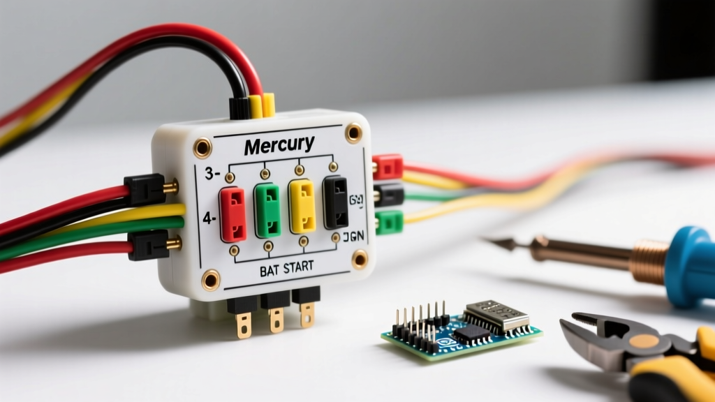
Most Chevy 350 industrial setups utilize a Delco PG260 gear-reduction starter. The starter solenoid features three terminals: the large BAT post, the small 'S' (switch) terminal, and the often-ignored 'R' (relay) terminal.
During engine cranking, the starter draws 150 to 250 amps, causing massive voltage drop across the battery and main ignition switch. If the HEI distributor is only receiving power from the ignition switch, voltage at the coil may drop below 9V during cranking, resulting in a weak spark and a flooded engine.
The Fix: Run a 14 AWG wire from the starter solenoid's 'R' terminal directly to the HEI 'BATT' terminal. The 'R' terminal only outputs full battery voltage while the starter is actively engaged. This provides a dedicated, unresisted 12V 'hot shot' to the ignition coil exclusively during cranking, bypassing any voltage drop in the main harness.
Wire Gauge & Component Selection Matrix
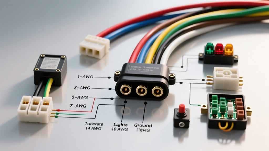
When wiring a standalone engine appliance, adhering to proper wire gauge and insulation types is critical to prevent electrical fires. The following matrix is based on SAE J1128 standards for high-temperature engine bay environments.
| Circuit Application | Wire Gauge (AWG) | Insulation Type | Max Ampacity | Overcurrent Protection |
|---|---|---|---|---|
| Battery to Starter Solenoid | 2 AWG or 1/0 AWG | SXL or THHN | 250A+ (Cranking) | None (Fusible Link at Battery) |
| Alternator Main Output (BAT) | 8 AWG or 6 AWG | SXL | 60A - 100A | Mega Fuse (120A) |
| HEI Ignition Feed | 12 AWG | SXL or GXL | 20A | 20A ATC Blade Fuse |
| Starter 'R' to HEI Bypass | 14 AWG | SXL | 15A | None (Momentary Circuit) |
| Oil Pressure Safety Shutoff | 16 AWG | TXL | 10A | 10A Inline Fuse |
Safety Shutoffs & NFPA 70 Compliance
When wiring a Chevy 350 as a stationary generator or pump, you must adhere to safety standards governing prime movers. According to the NFPA 70 National Electrical Code (NEC), specifically Article 445 regarding generators, stationary engines must be equipped with automatic shutdown mechanisms for low oil pressure and high coolant temperature.
Wiring the Safety Interrupt Circuit
To implement this on a standalone HEI system, you will use a dual-circuit safety relay or a heavy-duty automotive relay (e.g., Bosch 0332014150, 30A).
- Oil Pressure Switch: Use a normally-closed (NC) switch that opens at 8 PSI. Wire this in series with the HEI ground trigger or use it to cut power to the main ignition relay.
- Temperature Switch: Use a normally-open (NO) switch that closes at 220°F. Wire this to trigger a relay that grounds the HEI tach signal, instantly killing the spark without shorting out the 12V feed.
- Magneto Kill Switch: Never ground the HEI 'BATT' terminal to kill the engine; this will fry the internal pickup coil. Instead, install a switch that interrupts the 12V feed before it reaches the distributor.
Troubleshooting Common Standalone Failures
Even with a perfect wiring diagram for Chevy 350 setups, industrial environments introduce unique failure modes. Use this diagnostic matrix to resolve common electrical anomalies.
| Symptom | Root Cause Analysis | Corrective Action |
|---|---|---|
| HEI Module fails repeatedly after 2-5 hours of runtime. | Thermal runaway. The 4-pin module relies on the distributor base as a heatsink. Lack of thermal interface compound causes internal silicon meltdown. | Remove module, clean housing, and apply a generous layer of zinc-oxide thermal heat sink grease (e.g., Wakefield-Vette 120-2) before reinstalling. |
| Alternator whines and battery drains at low idle (800 RPM). | 1-wire alternator requires higher RPM to self-excite due to weak residual magnetism in the rotor. | Switch to a 3-wire configuration with an ignition-switched exciter wire, or install a smaller alternator pulley to increase rotor speed at idle. |
| Engine backfires through carburetor during cranking but runs fine once started. | Severe voltage drop across the ignition switch during cranking starves the HEI coil, resulting in a weak spark and improper timing advance. | Verify the 'R' terminal bypass wire from the starter solenoid is securely connected to the HEI BATT terminal and is free of corrosion. |
Final Assembly & Conduit Routing
Once the wiring diagram for your Chevy 350 appliance is executed, physical routing is your final hurdle. Never zip-tie wiring directly to exhaust manifolds or sharp casting edges. Use split-loom corrugated tubing rated for 150°C, and secure the harness using aluminum P-clamps with rubber cushions. For the ultimate industrial finish, consider wrapping the main harness in Techflex fiberglass sleeving, which provides complete immunity to radiant heat from the SBC's exhaust crossover.
By treating the Chevy 350 not as a car engine, but as a dedicated industrial appliance, and by strictly adhering to heavy-duty wire gauges and remote-sensing alternator topologies, you ensure your power plant will run reliably for thousands of hours in the field.