
Designing a Safe Wiring Diagram for Boat Switch Panel Systems
Marine environments are notoriously unforgiving. Saltwater intrusion, constant vibration, and UV exposure demand strict adherence to electrical safety protocols. When drafting a wiring diagram for boat switch panel layouts, selecting the correct wire gauge and adhering to standardized marine color codes is not merely an aesthetic choice—it is a critical defense against electrical fires, stray current corrosion, and catastrophic equipment failure.
As of 2026, the American Boat & Yacht Council (ABYC) E-11 standard remains the definitive benchmark for marine DC electrical systems. Unlike automotive wiring, marine wiring requires tinned copper conductors and specific insulation ratings (UL 1426 or SAE J378) to resist moisture and electrolysis. This guide provides a comprehensive, expert-level reference for wire gauge selection, ABYC color codes, and physical termination protocols for modern marine switch panels.
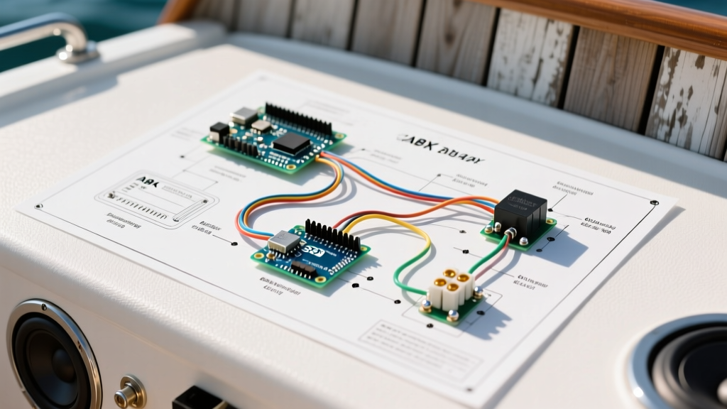
Core Topology: Battery to Switch Panel Routing
Before selecting wire colors and gauges, your wiring diagram must reflect a logically protected topology. A standard marine DC system should never run loads directly from the battery without primary overcurrent protection.
- Primary Protection: A Class T fuse or main circuit breaker installed within 7 inches of the battery positive terminal.
- Distribution: Power routes to a positive bus bar (e.g., Blue Sea Systems PowerBar), which then feeds the main breaker on the switch panel.
- Switch Panel Integration: Modern panels (like the BEP Marine C-Zone or Blue Sea WeatherDeck) feature integrated or secondary breakers for individual branch circuits.
- Return Path: All negative returns must route to a dedicated negative bus bar, never daisy-chained to engine blocks or fuel tanks.
ABYC Marine Wire Color Code Standards
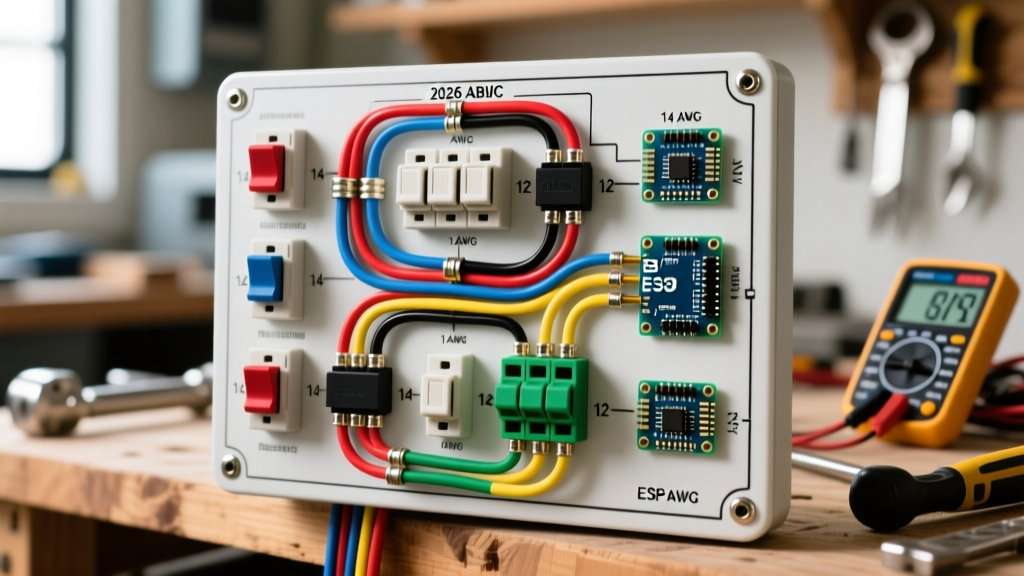
Consistent color coding is essential for troubleshooting and preventing dangerous cross-wiring. The ABYC E-11 standard dictates specific colors for DC systems. While custom yachts may use multi-colored Deutsch connector pigtails, the primary branch wiring from the switch panel to the load must follow these conventions.
| Color | Abbreviation | Application / Function | Typical Switch Panel Load |
|---|---|---|---|
| Red | R | Positive Mains, Unprotected Positive | Main Panel Feed, Battery Switch |
| Yellow | Y | Starting, Blower, Ignition, Alternator | Engine Blower, Ignition Switch |
| Black | B | Negative Ground / Return | All DC Load Returns |
| Yellow w/ Red Stripe | YR | Ignition, Start Solenoid, Accessories | Accessory Sockets, Stereo Memory |
| Dark Blue | DB | Navigation Lights, Cabin Lights | LED Nav Lights, Interior Illumination |
| Light Blue | LB | Oil Pressure, Fuel Gauge Senders | Instrument Panel Illumination |
| Orange | O | Distribution, Common Feeds, Amps | Bilge Pump Auto Feed (Unswitched) |
| Green | G | DC Grounding (Bonding System) | Fuel Tank Bonding, Lightning Ground |
Expert Note on Bonding: Never confuse the DC negative ground (Black) with the DC grounding/bonding system (Green). The green wire connects metallic non-current-carrying parts to the common ground point to prevent shock hazards and galvanic corrosion. For detailed bonding schematics, refer to the ABYC Standards documentation.
Calculating Wire Gauge for Marine Branch Circuits
Automotive wire sizing charts are dangerously inadequate for boats. Marine wire gauge is dictated by voltage drop over the total round-trip circuit length (positive wire + negative return wire). According to the US Coast Guard Boating Safety guidelines and ABYC standards, voltage drop must be strictly managed:
- 3% Maximum Drop: Mandatory for navigation lights, marine electronics (VHF, GPS, Sonar), and sensitive communication equipment.
- 10% Maximum Drop: Acceptable for general loads like cabin lighting, bait pumps, and windlasses.
Real-World Gauge Selection Matrix (12V DC System)
The following matrix assumes a standard 12V DC system and utilizes Type III marine-grade tinned copper wire. Distances represent the total round-trip length from the switch panel to the load and back to the negative bus bar.
| Load Current (Amps) | 10 ft Round Trip | 20 ft Round Trip | 40 ft Round Trip | Typical Marine Application |
|---|---|---|---|---|
| 5A | 16 AWG | 14 AWG | 10 AWG | LED Nav Lights, VHF Radio |
| 10A | 14 AWG | 12 AWG | 8 AWG | Cabin Fans, Stereo Amplifiers |
| 15A | 12 AWG | 10 AWG | 6 AWG | Bilge Pumps, Horns, Wipers |
| 20A | 10 AWG | 8 AWG | 4 AWG | Anchor Windlass Controls, Inverters |
| 30A+ | 8 AWG | 6 AWG | 2 AWG | Main Panel Feeds, Heavy Winches |
The Cost of Compromise: Untinned vs. Tinned Copper
In 2026, the price gap between automotive (untinned) and marine (tinned) wire has narrowed, with premium brands like Ancor and Pacer Group pricing 12 AWG marine wire at approximately $0.55 to $0.75 per foot. Untinned copper rapidly oxidizes in salt air, turning black and increasing electrical resistance. This phenomenon, known as "black wire syndrome," causes voltage drops and generates excess heat at the switch panel terminals. Always specify UL 1426 tinned copper wire for your wiring diagram.
Step-by-Step Panel Termination & Heat Shrink Protocols
A flawless wiring diagram is useless if the physical terminations fail. The vibration of a planing hull will loosen poorly crimped connectors, leading to arcing. Follow this exact termination sequence for switch panel connections:
- Strip the Insulation: Use a precision wire stripper (e.g., Knipex MultiStrip 10) to avoid nicking the tinned copper strands. Nicked strands create localized resistance points that will overheat under load.
- Select the Terminal: Use only marine-grade, heat-shrink insulated ring terminals. The nylon insulation should match the wire gauge (Red for 22-16 AWG, Blue for 16-14 AWG, Yellow for 12-10 AWG).
- Crimp with Precision: Use a dedicated ratcheting crimper like the IWISS SN-48B or the Knipex 48 11 J2. The ratchet mechanism ensures the exact compression ratio required for a gas-tight connection. A gas-tight crimp prevents oxygen and moisture from entering the wire barrel.
- Apply Adhesive Heat Shrink: This is the most critical step. Apply heat evenly until the adhesive lining melts and flows out of the ends. This polyamide adhesive creates a waterproof seal that prevents capillary action from drawing moisture up into the wire strands.
Common Failure Modes & Troubleshooting
Even with a perfect wiring diagram for boat switch panel setups, environmental factors can introduce faults. Here is how to diagnose the three most common marine electrical failures:
1. Stray Current Corrosion at the Panel
Symptom: Green/white powdery corrosion on the back of the switch panel bus bars and breaker terminals.
Cause: Bilge water splashing onto the panel, or inadequate adhesive sealing on crimp joints allowing moisture to wick into the copper.
Solution: Relocate the panel above the maximum anticipated bilge water line. Apply a dielectric grease (like Boeshield T-9 or NO-OX-ID) to all exposed bus bar threads and terminal studs after torquing the nuts to manufacturer specifications.
2. Voltage Drop Under Load
Symptom: Navigation lights dim when the bait pump activates, or the VHF radio resets during transmission.
Cause: Undersized wire gauge for the round-trip distance, or a high-resistance connection at the negative bus bar.
Solution: Perform a voltage drop test using a high-impedance multimeter (e.g., Fluke 87V). Measure across the positive wire and then across the negative wire while the load is active. A healthy connection should show less than 0.1V drop per connection point.
3. Thermal Runaway at Switch Terminals
Symptom: Discolored or melted plastic on the back of the switch panel breakers.
Cause: Loose crimps or overloading a continuous-duty circuit on a standard toggle switch.
Solution: Standard toggle switches are rated for intermittent use. For continuous loads exceeding 10A (like livewell pumps), your wiring diagram must incorporate a marine relay (e.g., Blue Sea Systems ML-ACR or a standard Bosch-style 40A marine relay), using the switch panel only to trigger the low-amperage relay coil.
Frequently Asked Questions (FAQ)
Can I use standard automotive wire for a boat switch panel?
No. Automotive wire (SAE J1128) uses untinned copper and insulation that is not rated for the continuous moisture and UV exposure found in marine environments. Using it violates ABYC standards and voids most marine insurance policies. Always use Type III marine-grade tinned wire.
Do I need a breaker for every switch on the panel?
Yes. Every ungrounded (positive) conductor must be protected by an overcurrent device (fuse or circuit breaker) rated for the ampacity of the smallest wire in that branch circuit. If your switch panel does not have integrated breakers, you must install an inline fuse holder or a secondary fuse block within 7 inches of the power source feeding the panel.
What is the best wire color for an always-on bilge pump?
According to ABYC color codes, Orange (O) is typically used for distribution and common feeds, including unswitched, always-on circuits like automatic bilge pumps. This ensures the pump remains active even when the main battery switch and switch panel are turned off.
Final Recommendations for 2026 Builds
When finalizing your wiring diagram for boat switch panel integration, prioritize serviceability. Label every wire at both the panel and the load using a marine-grade heat-shrink label printer (such as the Brady BMP21-PLUS with continuous marine-grade nylon tape). Keep a digital copy of your schematic, complete with exact wire lengths and breaker sizes, stored in a waterproof document holder near the helm. For further reading on marine electrical safety and certification requirements, consult the National Marine Electronics Association (NMEA) installation guidelines.