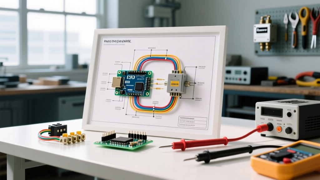

Understanding the Brain of Your Water System
When your well pump begins short-cycling, fails to engage, or runs continuously, the pressure switch is the primary component to investigate. Acting as the electromechanical brain of your private water system, this device monitors the hydrostatic pressure in your tank and triggers the 240V (or 120V) pump circuit. However, blindly swapping parts without understanding the circuit can lead to misdiagnosed failures, destroyed pump motors, or dangerous electrical faults.
By learning how to read and apply a wiring diagram for a well pressure switch, you can isolate the exact point of failure. Whether you are dealing with a pitted contact, a clogged sensing port, or a failing tank bladder, the diagram provides the roadmap for systematic troubleshooting. In this guide, we will use the industry-standard Square D 9013FHG series (specifically the 9013FHG12J20M1 for 30/50 PSI systems) and the Condor MDR 11 as our reference models to break down real-world diagnostics.
Anatomy of a Standard Pressure Switch Circuit
Before grabbing a multimeter, you must understand the physical layout of the switch and how it maps to the schematic. Most residential well systems operate on a 240V, single-phase, 30-amp dedicated circuit. According to the National Electrical Code (NEC), the metal enclosure of the pressure switch must be properly bonded to the equipment grounding conductor to prevent shock hazards in damp well-house environments.
Line vs. Load Terminals
A standard wiring diagram for a well pressure switch will clearly delineate between the power source and the pump motor:
- Line Terminals (L1 & L2): These connect directly to the incoming power from the double-pole breaker in your main or sub-panel. They are 'hot' at all times when the breaker is ON.
- Load Terminals (T1 & T2): These connect to the well pump motor. Power only flows to these terminals when the internal contacts are closed (i.e., when water pressure drops below the cut-in threshold).
- Ground (Green Screw): Connects the bare copper or green insulated grounding wire from the panel and the ground wire leading down the well casing to the pump.
Decoding the Wiring Diagram: Terminal Mapping Matrix
When you open the switch cover, the physical terminals might not explicitly say 'Line' or 'Load'. Use this matrix to map the schematic symbols to the physical switch:
| Diagram Symbol | Physical Terminal Label | Wire Color (Typical 10/2 AWG) | Function |
|---|---|---|---|
| L1 (Source) | Left Brass Screw (Top) | Black (Incoming) | 120V Leg 1 from Breaker |
| L2 (Source) | Right Brass Screw (Top) | White/Red (Incoming) | 120V Leg 2 from Breaker |
| T1 (Load) | Left Brass Screw (Bottom) | Black (To Pump) | 120V Leg 1 to Motor |
| T2 (Load) | Right Brass Screw (Bottom) | White/Red (To Pump) | 120V Leg 2 to Motor |
| GND | Green Hex Screw (Enclosure) | Bare Copper | Equipment Grounding |
Step-by-Step Troubleshooting Using the Diagram
With the schematic in mind, we can move to live testing. Safety Warning: You will be testing live 240V circuits. Use a True RMS multimeter (like the Fluke 117) with CAT III or CAT IV ratings, and wear insulated gloves.
Scenario 1: The Pump is Completely Dead
Symptom: You open a faucet, pressure drops to zero, and the pump does not turn on.
Diagram Trace: Follow the path from L1/L2 through the internal contacts to T1/T2.
Troubleshooting Steps:
- Set your multimeter to AC Voltage (V~).
- Measure across L1 and L2. You should read ~240V. If you read 0V, the issue is upstream (tripped breaker, broken wire in the trench).
- If L1-L2 reads 240V, manually press the internal contactor plate down with an insulated tool. If the pump kicks on, your electrical circuit is fine, but your mechanical sensing is blocked.
- Check the 1/4 inch brass nipple connecting the switch to the tank tee. Galvanic corrosion and iron bacteria frequently clog this port, preventing water pressure from reaching the internal diaphragm. Replace the nipple ($3 part) and clear the port with a wire.
Scenario 2: Severe Short-Cycling (Rapid On/Off)
Symptom: The pump clicks on and off every 3 to 10 seconds while water is running.
Diagram Trace: The contacts are opening and closing rapidly due to instantaneous pressure spikes and drops.
Troubleshooting Steps:
Short-cycling is rarely an electrical wiring fault; it is almost always a hydraulic failure that the wiring diagram helps you rule out. If voltage at T1/T2 is stable and matching the rapid clicking, the switch is doing its job perfectly. The fault lies in the pressure tank. A ruptured butyl bladder or a completely waterlogged tank (loss of air charge) causes immediate pressure spikes when the pump runs, tripping the switch open instantly. Recharging the tank to 28 PSI (for a 30/50 switch) with an air compressor usually resolves this. If the bladder is torn, expect to spend $150 to $300 on a replacement tank.
Scenario 3: Pump Runs Continuously (Won't Shut Off)
Symptom: Pressure gauge reads 60+ PSI, water is spraying from the pressure relief valve, but the pump keeps running.
Diagram Trace: The circuit between L1/L2 and T1/T2 is permanently closed, ignoring the mechanical spring tension.
Troubleshooting Steps:
- Turn off the breaker immediately to prevent pipe bursts.
- Open the switch cover and inspect the silver cadmium contacts. Heavy arcing over years of use can cause the contacts to physically weld (fuse) together. If they are pitted or fused, the $30 switch must be replaced.
- If the contacts are separated but the pump still runs when power is restored, check for a short circuit in the underground wiring between the switch and the wellhead. A melted 10 AWG UF-B cable shorting T1 to T2 bypasses the switch entirely.
Multimeter Diagnostic Matrix
Use this quick-reference table when testing your pressure switch with a digital multimeter. Ensure the system is under low pressure (below the cut-in setting, e.g., below 30 PSI) so the switch contacts are mechanically closed.
| Test Point | Multimeter Setting | Expected Reading (Contacts Closed) | Fault Indication |
|---|---|---|---|
| L1 to L2 | AC Voltage | 235V - 245V | Upstream breaker or utility issue if 0V or 120V. |
| L1 to Ground | AC Voltage | ~120V | Missing ground or open neutral if 0V. |
| T1 to T2 | AC Voltage | 235V - 245V | Bad internal contacts or loose terminal screws if 0V. |
| T1 to Ground | Continuity (Ohms) | OL (Open Loop / Infinite) | Dead short to ground in well wiring if near 0 Ohms. |
The Hidden Culprit: Adjusting the Springs
Sometimes, the wiring is flawless, but the switch calibration is wrong. Under the plastic cover of a Square D 9013FHG, you will find two nuts on threaded posts:
- The Tall Post (Range Spring): Adjusts both the cut-in and cut-out pressures simultaneously. Turning the 3/8 inch hex nut clockwise increases the overall pressure range.
- The Short Post (Differential Spring): Adjusts ONLY the cut-out pressure, widening or narrowing the gap between the on and off thresholds.
Expert Tip: Never adjust the differential spring to achieve a cut-out pressure higher than your pump's maximum dead-head capability. If you set a switch to 40/80 PSI, but your shallow-well jet pump maxes out at 65 PSI, the pump will run endlessly, overheat, and destroy its start capacitor. Always verify your pump curve before altering spring tension.
When to Repair vs. Replace
Pressure switches are not designed to be rebuilt. The internal contacts are precision-aligned to quench the electrical arc that occurs when breaking a 240V inductive motor load. If the contacts are heavily pitted, blackened, or if the internal diaphragm is leaking water into the electrical cavity, replace the entire unit. A standard Square D 30/50 PSI switch costs between $28 and $42 at most electrical suppliers in 2026, making repair an unsafe and uneconomical endeavor.
For comprehensive maintenance guidelines on private water systems, including protecting your electrical components from environmental hazards, refer to the EPA Private Wells Guide. Additionally, understanding the broader context of well system failures can help you diagnose whether a switch issue is a root cause or a secondary symptom, as detailed by InterNACHI's well inspection standards.
Summary
Mastering the wiring diagram for a well pressure switch transforms a frustrating loss of water into a logical, 15-minute diagnostic procedure. By verifying incoming voltage at the Line terminals, testing outgoing voltage at the Load terminals, and understanding the mechanical limits of the sensing port, you can accurately pinpoint whether the fault lies in the panel, the switch, the tank, or the well pump itself. Always prioritize safety, lock out the breaker before tightening terminal screws, and rely on your multimeter to reveal the truth hidden inside the enclosure.