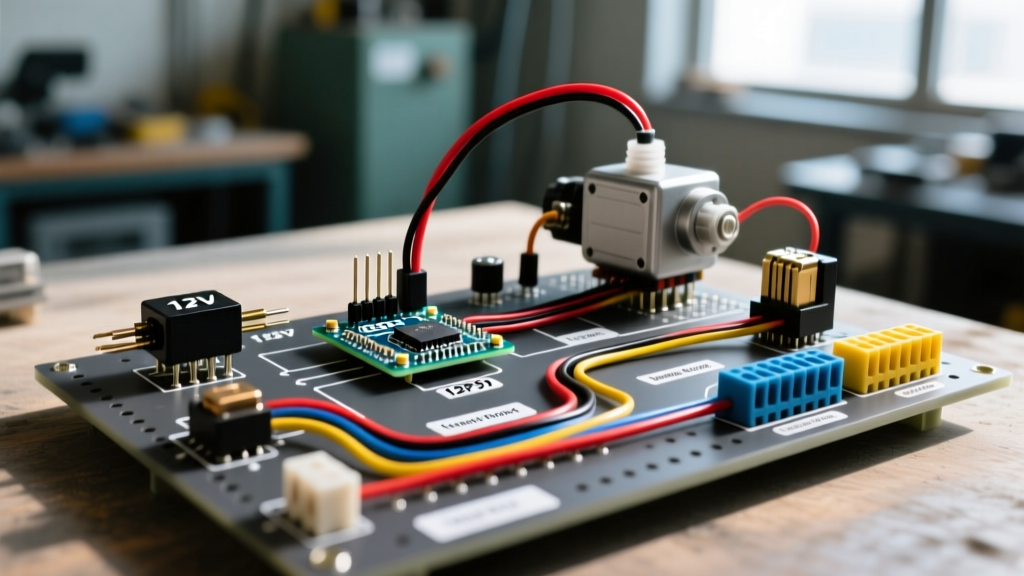

The Hidden Dangers of Direct-Switch Fuel Pump Wiring
Wiring an aftermarket 12V electric fuel pump directly to a toggle switch, ignition switch, or oil pressure sender is a critical failure point in custom automotive, marine, and generator builds. High-flow EFI pumps like the Bosch 044 or even standard carburetor pumps like the Facet 40105 draw sustained amperage that standard dashboard switches and thin factory ignition wires cannot handle. This results in severe voltage drop, melted wiring harnesses, and in worst-case scenarios, electrical fires.
A proper electric fuel pump wiring diagram must incorporate a heavy-duty ISO relay, an appropriately rated inline fuse, and a crash-activated inertia cutoff switch. This guide details the exact components, wire gauge requirements, and step-by-step routing necessary to build a reliable, safe, and high-performance fuel delivery circuit compliant with modern automotive safety standards.
Essential Components for a Safe 12V Fuel Pump Circuit
Before cutting or crimping any wire, gather the correct hardware. Using undersized components is the primary cause of premature pump failure due to voltage starvation. As of 2026, here are the industry-standard components and their approximate costs for a professional-grade setup:
- The Fuel Pump: For high-pressure EFI (43+ PSI), the Bosch 044 (approx. $190-$220) is the benchmark, drawing up to 18 amps under load. For low-pressure carburetor setups (4-7 PSI), the Carter P4070 (approx. $55) or Facet 40105 (approx. $45) draw only 3 to 4 amps. For authoritative specs on pump variations, refer to Carter Fuel Systems.
- The Relay: Use a standard 5-pin ISO mini relay, such as the Bosch 0332014150 (rated for 30A/40A, approx. $10). Detailed relay load tolerances can be verified via Bosch Motorsport Relays.
- The Fuse: ATO/ATC blade fuses are suitable for low-amp carburetor pumps. For high-amp EFI pumps, use a MIDI or MAXI fuse holder with a 25A or 30A fuse.
- Inertia Cutoff Switch: A standard Ford 3-pin inertia switch (e.g., F6SZ-9A276-AA, approx. $15) cuts power to the pump instantly upon sudden deceleration or impact, preventing fuel from spraying in a collision.
- Connectors & Wire: Avoid soldering under-hood wiring; vibration causes solder joints to fatigue and snap. Use a ratcheting crimper (like the Delphi 12014254 tool) with sealed Weather-Pack or Deutsch DT connectors.
Step-by-Step Electric Fuel Pump Wiring Diagram Guide
The following sequence outlines the exact routing for a standard 12V DC fuel pump circuit utilizing a 5-pin ISO relay. This configuration ensures the heavy current load bypasses the vehicle's delicate ignition switch entirely.
Step 1: The High-Amperage Power Circuit (Pins 30 & 87)
- Pin 30 (Power In): Run a primary power wire directly from the positive terminal of the battery (or the main starter lug). Crucial: Install an inline fuse holder within 6 inches of the power source. This protects the entire length of the wire in case of a short to ground. Connect this fused wire to Pin 30 on the relay.
- Pin 87 (Power Out): Run a wire from Pin 87 to the positive terminal of the electric fuel pump. If you are integrating an inertia switch or an oil-pressure safety switch, wire it in-line on this specific leg (between Pin 87 and the pump).
Step 2: The Low-Amperage Trigger Circuit (Pins 85 & 86)
- Pin 86 (Switched Power): Connect a lighter-gauge wire to a 12V ignition-switched source (e.g., the fuel pump prime wire from an ECU, or an ignition-run circuit). This provides the low-amp signal to energize the relay coil.
- Pin 85 (Ground): Connect this pin to a clean, bare-metal chassis ground. Do not rely on painted surfaces or factory ground clusters that may be shared with sensitive ECU sensors, as this can introduce electrical noise.
Step 3: Grounding the Fuel Pump
The fuel pump itself must be grounded locally. Run a dedicated ground wire from the pump's negative terminal to a clean, unpainted metal point on the chassis or fuel tank sender ring. Seal the crimp connection with marine-grade heat shrink to prevent corrosion from road salt and moisture.
Code Compliance Note: When routing DC wiring through metal firewalls or bulkheads, always use rubber grommets to prevent insulation chafing. Adhering to chassis grounding and overcurrent protection guidelines aligns with best practices outlined in the NFPA 70 National Electrical Code for mobile and specialized DC applications.
Wire Gauge and Voltage Drop Matrix
Voltage drop is the silent killer of electric fuel pumps. If a pump rated for 13.5V receives only 11V due to undersized wiring, its flow rate drops exponentially, and the internal armature will overheat and fail prematurely. Use the matrix below to select the correct copper wire gauge (AWG) based on your pump's maximum amperage draw and the total round-trip wire length (from battery, to pump, and back to ground).
| Pump Type / Model | Max Amps | Total Wire Length (ft) | Minimum Wire Gauge (AWG) | Target Voltage Drop |
|---|---|---|---|---|
| Facet 40105 / Carter P4070 | 4A - 5A | Under 10 ft | 16 AWG | < 0.2V |
| Facet 40105 / Carter P4070 | 4A - 5A | 10 ft - 20 ft | 14 AWG | < 0.3V |
| Walbro 255 / AEM 340 | 12A - 14A | Under 15 ft | 12 AWG | < 0.4V |
| Walbro 255 / AEM 340 | 12A - 14A | 15 ft - 25 ft | 10 AWG | < 0.5V |
| Bosch 044 / Fuelab Pro | 18A - 22A | Under 15 ft | 10 AWG | < 0.4V |
| Bosch 044 / Fuelab Pro | 18A - 22A | 15 ft - 25 ft | 8 AWG | < 0.5V |
Note: Always calculate using the total circuit length (positive wire + negative wire). If your pump is 10 feet from the battery, the total circuit length is 20 feet.
Integrating the Inertia Cutoff Switch
An inertia switch is a mandatory safety device in many racing sanctions and marine applications. It contains a steel ball held in place by a magnet; upon sudden impact, the ball breaks free and opens the electrical contacts, killing power to the fuel pump.
Wiring the Inertia Switch
The standard Ford-style inertia switch has three pins: one common, one normally-closed (NC), and one normally-open (NO). You must wire the switch into the Pin 87 (Load) side of the relay circuit using the Common and NC pins.
- Why not the trigger side (Pin 86)? If you place the inertia switch on the low-amp trigger side, the relay contacts (Pin 30 to 87) remain physically closed as long as the ignition is on. In a severe crash where the relay housing fractures or the trigger wire shorts, the pump could continue running. Placing it on the high-amp load side guarantees the physical path to the pump is severed.
Advanced Troubleshooting: Load Testing & Ground Loops
If your newly wired fuel pump is noisy, runs hot, or fails to maintain fuel pressure, do not immediately replace the pump. Perform these diagnostic steps with a digital multimeter (DMM):
1. The Loaded Voltage Drop Test
Static voltage readings are deceptive. A frayed wire might show 12.6V with the pump disconnected, but drop to 9V when the pump draws 15 amps under load.
- Turn the ignition on to prime the pump.
- Set your DMM to DC Volts.
- Place the red probe directly on the pump's positive terminal and the black probe directly on the pump's negative terminal.
- If the reading is below 12.0V (or more than 0.5V lower than battery voltage), you have a restriction. Move the probes outward toward the battery to isolate whether the voltage drop is occurring on the power side or the ground side.
2. Diagnosing Relay Chatter
If your relay is clicking rapidly (chattering), it is usually caused by a voltage drop in the trigger circuit (Pin 86). If the ECU prime wire or ignition switch cannot supply adequate amperage to hold the relay coil closed, the relay will flutter. Fix: Add a secondary "bridge" relay to multiply the trigger current, or install a 1000µF capacitor across Pins 85 and 86 to stabilize the coil voltage.
3. Ground Loop Interference
If you are experiencing erratic fuel trims or ECU sensor errors after wiring a high-amperage fuel pump, the pump's ground current may be flowing through the ECU's sensor ground path. Always ensure the fuel pump ground is bolted directly to the chassis or engine block, completely isolated from the ECU's dedicated ground star-point.