
The Electrical Anatomy of a Reverse Camera Circuit
Upgrading or replacing a backup camera requires more than just plugging in an RCA cable. As any seasoned automotive electrician will tell you, treating low-voltage camera wiring with the same rigor as high-current motor wiring is the secret to a flicker-free, long-lasting installation. The NHTSA Rear Visibility Standards mandate these systems on all modern vehicles, meaning understanding the underlying electrical architecture is essential for both repairs and aftermarket upgrades.
A standard reverse camera for car wiring diagram revolves around four primary circuit paths:
- 12V+ Power (Red): Typically draws between 120mA and 250mA. Powers the camera's internal CMOS sensor and IR LEDs.
- Chassis Ground (Black): Completes the circuit. Must be tied to bare, unpainted metal to prevent voltage drop.
- Video Signal (RCA Center Pin): Carries the NTSC/PAL analog composite or AHD (Analog High Definition) signal.
- Reverse Trigger (Flying Lead): A low-current signal wire that tells the head unit to switch the display to the camera feed.
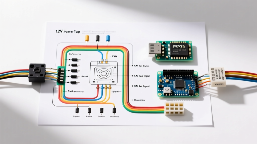
Standard 12V Reverse Light Tap (Legacy & Standard Vehicles)
For vehicles manufactured prior to the widespread adoption of multiplexed CAN-bus systems (generally pre-2015, and many non-European models up to 2026), the reverse light circuit provides a clean, steady 12V DC signal when the transmission is shifted into reverse.
Step-by-Step Tapping Procedure
- Identify the Wire: Remove the interior trunk trim to access the taillight harness. Use a Digital Multimeter (DMM) set to DC 20V. Probe the wires at the reverse bulb socket while the vehicle is in reverse (engine running to simulate real-world 14.2V alternator output).
- Make the Connection: Never use cheap vampire T-taps. They fray copper strands and invite corrosion. Instead, use a Posi-Tap connector (Part #2022 for 18-24 AWG). These cost roughly $4 each but provide a gas-tight, vibration-proof connection that rivals OEM motor wiring harnesses.
- Route the Trigger: Connect the camera-end flying lead to the Posi-Tap. Run the RCA cable and the head-unit-end flying lead through the vehicle's interior grommets.
The CAN-Bus & PWM Hurdle in Modern Vehicles
If you are installing a camera in a modern European vehicle (VW, Audi, BMW) or late-model American trucks (2019-2026 Ram 1500, Ford F-150), you will likely encounter Pulse Width Modulation (PWM) on the reverse light circuit. The vehicle's Body Control Module (BCM) rapidly pulses the voltage to monitor bulb resistance and detect outages.
Expert Insight: A standard aftermarket camera requires a steady minimum of 9V to keep its internal voltage regulator engaged. A PWM signal drops to 0V dozens of times per second. If you tap a PWM reverse light directly, your camera will flicker violently, shut off, or display a "No Signal" error on your head unit.
The Fix: 12V DC Filter Relay or CAN-Bus Decoder
To solve this, you must isolate the camera from the BCM's pulsed signal. You have two options:
- Option A (The Relay Method - $8): Wire a standard 12V automotive Bosch-style relay. Connect the PWM reverse light wire to the relay coil (Terminal 86). Ground Terminal 85. Run a fused, steady 12V ignition source to Terminal 30. Connect the camera's 12V+ and Trigger wire to Terminal 87. The coil absorbs the PWM noise, and the contacts output a clean, steady 12V to the camera.
- Option B (CAN-Bus Decoder Module - $25 to $45): Purchase a dedicated CAN-bus reverse light adapter (such as the PAC TR-4 or OEM-specific harness). These solid-state modules contain built-in capacitors that smooth the PWM ripple into a flat DC line without the clicking noise of a mechanical relay.
Motor Bay & Chassis Routing: The Professional Standard
While camera wires carry minimal current, they must be routed with the same physical protections as high-amperage motor wiring. The undercarriage and trunk hinge areas are hostile environments.
Routing Matrix & Protection Specs
| Routing Zone | Hazard | Required Protection |
|---|---|---|
| Trunk Lid Hinge | Pinching / Wire Fatigue | Flexible rubber loom; leave 2 inches of slack; secure with adhesive-backed zip ties every 6 inches. |
| Underbody / Chassis | Road Debris / Water | Split-loom tubing wrapped in Tesa 51036 PET cloth tape (prevents rattling and abrasion). |
| Proximity to Exhaust | Melting / Heat Degradation | Minimum 6-inch clearance. If unavoidable, use fiberglass heat-shield sleeving rated to 500°F. |
| Firewall / Grommet Pass | Short Circuit on Sharp Metal | Use a 15/16" rubber grommet. Never push bare wires through sheet metal. |
Head Unit Trigger Integration
According to the Crutchfield Backup Camera Installation Guide, properly triggering the aftermarket head unit is where most DIYers fail. The head unit needs to know when to switch the screen. For a comprehensive look at automotive circuits, referencing AA1Car Automotive Electrical Basics can help you trace factory harnesses.
Common Head Unit Reverse Wire Colors
- Pioneer: Purple/White (Usually labeled "REV")
- Alpine: Orange/White
- Kenwood / JVC: Purple/White or dedicated RCA trigger shield
- Sony: Orange/White
Note: If your RCA cable has a flying lead on both ends, the camera-end lead connects to the reverse light 12V+, and the head-unit-end lead connects to the head unit's reverse trigger wire. This completes the trigger circuit.
Troubleshooting Common Failure Modes
Even with a perfect wiring diagram, edge cases occur. Use this diagnostic framework before tearing apart your dashboard.
Symptom: Alternator Whine in Audio or Video Rolling Bars
Cause: Ground loop. The camera's ground and the head unit's ground are at slightly different electrical potentials, causing 60Hz+ AC noise to bleed into the RCA shield.
Fix: Ensure both the camera and head unit share the same chassis ground point, or install a $12 RCA Ground Loop Isolator inline at the back of the head unit.
Symptom: Camera Works, But Head Unit Doesn't Auto-Switch
Cause: The head unit's reverse trigger setting is disabled in the software menu, or the trigger wire is tapped to a constant 12V source instead of the reverse circuit.
Fix: Navigate to the head unit's hidden settings menu (e.g., Pioneer: Hold the home button, navigate to System Settings -> Camera -> Reverse Polarity -> Set to "Battery" or "Ground" depending on your trigger setup). Verify the trigger wire only sees 12V when the transmission is in Reverse.
Symptom: Image is Upside Down or Mirrored
Cause: Incorrect loop-back wire configuration on the camera pigtail.
Fix: Most universal cameras have two small green and white loop wires near the camera housing. Snipping one flips the image vertically; snipping the other mirrors it horizontally. Consult the camera's specific datasheet before cutting.
Final Verification Checklist
Before reassembling the trunk trim and dashboard, perform a final voltage drop test. With the engine running and the car in reverse, measure the voltage directly at the camera's power pigtail. It should read no less than 13.8V. If it reads lower, you have excessive resistance in your ground connection or your 12V tap. Secure all harnesses, apply dielectric grease to all exterior connections, and enjoy a factory-grade installation that will reliably last the life of the vehicle.