
Why Planning Precedes the Wiring Diagram for Contactor Integration
Translating a schematic into a physical, reliable control circuit requires meticulous pre-installation planning. Whether you are upgrading a 3-ton residential HVAC condenser or commissioning an industrial 480V motor starter, misinterpreting a wiring diagram for contactor layouts leads to catastrophic failures, including welded contacts, coil burnouts, and catastrophic arc flashes. In 2026, with the widespread adoption of IoT-enabled motor controllers and stricter energy efficiency mandates, the physical installation must perfectly mirror the engineered schematic.
This installation planning guide dissects the critical parameters you must verify before stripping a single wire. We will cover NEMA versus IEC sizing paradigms, precise termination torque specifications, control circuit isolation, and the most common edge cases that cause field failures.
Decoding Standard Contactor Schematics: Beyond the Basics
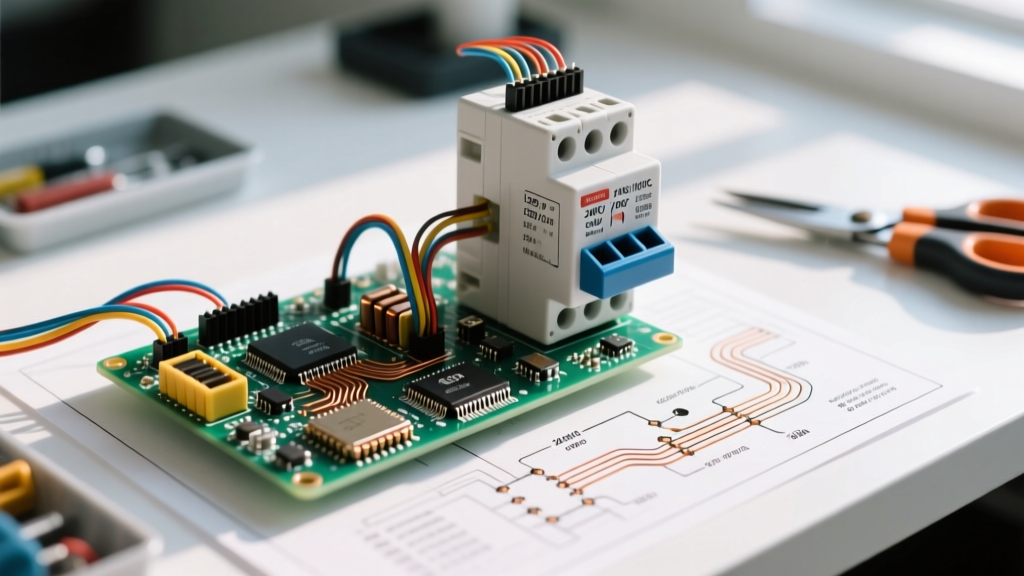
A standard wiring diagram for contactor components uses universally recognized IEC and NEMA symbols. However, field technicians often confuse auxiliary contact logic with primary power routing. Before planning your wire runs, verify these terminal designations on your specific schematic:
- Primary Power (L1, L2, L3 / T1, T2, T3): Line (source) and Load (motor/compressor) terminals. Never reverse these in environments where the contactor might be backfed, as the arc chute design is directional.
- Coil Terminals (A1, A2): The electromagnetic actuation circuit. A1 is typically the positive or hot side, while A2 is the neutral or ground reference. Some modern solid-state contactors feature polarity-sensitive A1/A2 terminals when driven by DC PLC outputs.
- Auxiliary Contacts (NO/NC): Designated by two-digit numbers (e.g., 13/14 for Normally Open, 21/22 for Normally Closed). These are strictly for control logic and interlocking, never for primary load switching.
Component Selection Matrix: NEMA vs. IEC Sizing
When reviewing your wiring diagram for contactor specifications, you must ensure the physical component matches the load profile. North American HVAC systems predominantly use NEMA-rated Definite Purpose (DP) contactors, while industrial and commercial panels lean toward IEC-rated utilization categories (AC-3 for squirrel cage motors). Below is a 2026 planning matrix comparing standard market options:
| Parameter | Eaton C25DND230 (NEMA DP) | Schneider TeSys LC1D09 (IEC) |
|---|---|---|
| Application | Residential/Commercial HVAC Compressors | Industrial Motor Control & Automation Panels |
| Current Rating | 30A (FLA), 150A (LRA Inrush) | 9A (AC-3 at 480V), 25A (AC-1 Resistive) |
| Coil Voltage | 24V AC (Standard Thermostat) | 24V AC/DC (Wide-range electronic coil) |
| Estimated Cost (2026) | $18.00 - $26.00 | $55.00 - $85.00 |
| Auxiliary Contacts | Typically None (Add-on side blocks available) | Integrated 1 NO + 1 NC (Front mount expandable) |
For comprehensive component selection, always cross-reference the manufacturer's latest derating curves. You can verify current IEC specifications via the Schneider Electric TeSys D catalog, or review NEMA definite purpose ratings through the Eaton DP contactor database.
Control Circuit Planning: Matching the Coil to the Source
The most frequent point of failure in a contactor installation is a mismatch between the control circuit voltage and the coil rating. When planning your wire routing, adhere to these voltage-specific guidelines:
24V AC Systems (HVAC Standard)
Sourced directly from the condenser unit's step-down transformer. Ensure the transformer is rated for at least 75VA to handle the initial inrush current of the contactor coil, which can be 5 to 10 times higher than the sealed (holding) current. Use 18 AWG or 16 AWG stranded copper for thermostat and control runs under 50 feet.
24V DC Systems (PLC & Automation)
If your wiring diagram for contactor actuation originates from a Programmable Logic Controller (PLC) transistor output, you must use an interposing relay. Most PLC outputs max out at 0.5A, whereas a standard industrial contactor coil inrush can draw 1.5A. Failing to use an interposing relay will destroy the PLC output card.
120V AC / 208-240V AC Systems (Commercial)
Used in heavy commercial lighting panels and pump stations. Per the National Electrical Code (NEC), control circuits operating at line voltage must be routed in the same raceway as the power conductors to prevent inductive interference and ensure simultaneous disconnect capabilities.
Pre-Wiring Checklist & Torque Specifications
Improper termination is the leading cause of thermal runaway in contactor lug connections. As of the 2026 NEC cycle, documented torque verification is heavily scrutinized by inspectors. Use a calibrated inch-pound torque screwdriver and follow these baseline specifications (always verify against the component's data sheet):
- Wire Preparation: Strip 10 AWG wire to exactly 3/8 inch. Do not tin the wire ends with solder; solder creeps over time under the pressure plate, leading to a loose connection and subsequent arcing.
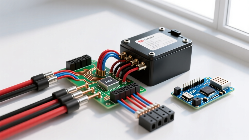
- Stranded vs. Solid: Use ferrules on all stranded control wires (14-18 AWG) terminating in A1/A2 screw-clamp terminals to prevent strand fraying and short circuits.
- Primary Lug Torque (10 AWG Copper): Tighten to 14-18 in-lbs. (e.g., Eaton C25 series).
- Primary Lug Torque (6 AWG Copper): Tighten to 35-40 in-lbs. for 40A-50A rated contactors.
- Control Terminal Torque (A1/A2): Typically 7-9 in-lbs. Overtightening will strip the brass threads or crack the phenolic coil housing.
- Pull Test: Apply a gentle, firm tug on every terminated wire to ensure the pressure plate has fully seated the conductor.
Edge Cases: Inrush Current and Contact Welding
Critical Warning: A contactor rated for 30A Full Load Amps (FLA) is not designed to switch a 30A resistive heater bank. Inductive motor loads have a high Locked Rotor Amps (LRA) inrush, but the inductive kickback actually helps extinguish the arc. Resistive loads do not have this inductive phase shift, causing severe contact pitting. Always check the AC-1 (resistive) vs AC-3 (inductive) ratings on your diagram.
When planning the installation, calculate the LRA of the compressor. If the LRA exceeds 600% of the FLA, and the system operates in a high-cycle environment (e.g., a commercial walk-in freezer with rapid door openings), the standard DP contactor will experience contact welding. In these edge cases, upgrade to an IEC-rated contactor with a higher AC-3 utilization category or install a solid-state contactor (SSR) that eliminates mechanical arcing entirely.
Troubleshooting Common Field Failures
Even with a perfect wiring diagram for contactor setups, field conditions introduce variables. Keep this diagnostic framework in your planning documentation:
- Humming/Buzzing Coil: Usually indicates undervoltage (below 85% of nominal rating) or debris on the magnetic pole faces. In 24V AC systems, a long, undersized thermostat wire run will cause severe voltage drop, starving the coil.
- Coil Burnout (Open Circuit): Caused by overvoltage, excessive ambient heat (above 55°C/131°F inside the panel), or mechanical binding preventing the armature from fully sealing.
- Phase Loss on T-Side: One set of primary contacts has pitted and failed to close. This single-phasing condition will destroy a 3-phase compressor motor within minutes if a phase-monitoring relay is not integrated into the auxiliary circuit.
Frequently Asked Questions
Can I wire a 120V coil contactor using a 24V thermostat?
No. You must use an interposing relay or a fan center with an integrated 24V-to-120V isolation relay. Directly wiring a 24V source to a 120V coil will result in the armature failing to pull in, leaving the circuit open while the coil slowly overheats and burns out.
Does the polarity matter on A1 and A2 for AC coils?
For standard 50/60Hz AC coils, polarity does not matter; A1 and A2 are interchangeable. However, if you are using modern electronic wide-range coils (e.g., 24-240V AC/DC) or solid-state contactors, A1 must be positive/line and A2 must be negative/neutral. Always read the 2026 manufacturer datasheet.
How do I wire auxiliary contacts for a run-light indicator?
Wire the indicator light through a Normally Open (NO) auxiliary contact block (terminals 13 and 14). Wire the line voltage to terminal 13, and the indicator light to terminal 14. The light will only illuminate when the contactor is fully engaged, providing accurate visual feedback of the motor's actual state, not just the command signal.