
The Definitive Motor Wiring Tutorial for the Yamaha G2 Electric
The Yamaha G2, produced between 1985 and 1990, remains one of the most iconic and mechanically straightforward golf carts ever built. For DIY restorers and fleet mechanics in 2026, the G2 Electric (G2E) is a highly sought-after platform. However, its unique 36-volt series-wound DC motor system and mechanical V-glide speed controller present specific wiring challenges that differ vastly from modern solid-state carts. Understanding the exact wiring diagram for Yamaha G2 golf cart motor systems is critical to preventing catastrophic electrical fires, solenoid welding, and premature motor burnout.
This comprehensive tutorial bypasses generic advice and dives deep into the exact terminal routing, wire gauge requirements, and failure-mode troubleshooting required to correctly wire, diagnose, and upgrade the Yamaha G2 electric drive system.
Anatomy of the G2 Electric Drive System
Before running a single wire, you must understand the five core components that dictate power flow in the G2E. Unlike modern carts that use a digital motor controller (MCOR), the G2 relies on mechanical resistance and field-tap switching.
- 36V Series-Wound DC Motor: Typically a Hitachi or Yamaha OEM 12T-3 motor featuring four main terminals (Armature and Field).
- Heavy-Duty Solenoid: A 36V continuous-duty relay that bridges the main battery pack voltage to the motor controller circuit.
- The V-Glide (Variable Resistor): A mechanical speed sensor that uses a resistive track and four microswitches to progressively alter motor speed.
- Forward/Reverse (F/R) Switch: A mechanical drum switch that reverses the polarity of the field coils relative to the armature to change direction.
- Microswitch Array: Safety and sequencing switches located at the throttle pedal and F/R lever to prevent solenoid arcing.
Battery Pack Configuration and Main Power Routing
The foundation of the wiring diagram for Yamaha G2 golf cart systems is the 36V battery bank, consisting of six 6-volt deep-cycle lead-acid batteries (or a modern 36V lithium drop-in equivalent). According to Batteries Plus wiring standards, improper series wiring is the leading cause of voltage drop and motor starvation.
Main Cable Specifications
Do not use standard automotive wire for the main drive loops. The G2 motor can pull upwards of 250 amps under heavy load or hill climbs.
| Circuit Path | Minimum Wire Gauge | Recommended Wire Gauge (2026 Std) | Terminal Torque Spec |
|---|---|---|---|
| Battery Pack Series Links | 4 AWG | 2 AWG OFC (Oxygen-Free Copper) | 90-110 in-lbs |
| Pack Positive to Solenoid | 4 AWG | 2 AWG OFC | 120 in-lbs |
| Solenoid to V-Glide/Motor | 4 AWG | 4 AWG OFC | 120 in-lbs |
| Motor to Pack Negative | 4 AWG | 2 AWG OFC | 120 in-lbs |
Decoding the Motor Terminals and Solenoid Routing
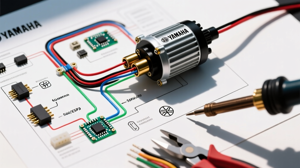
The heart of the motor wiring tutorial revolves around the four-post motor terminal block and the solenoid. The Yamaha G2 uses a series-wound motor, meaning the electrical current must flow through the field coils (stator) and the armature (rotor) in a continuous loop. For a deeper understanding of series-wound DC motor principles, refer to the foundational guides at Electrical Technology.
Motor Terminal Identification
Your Hitachi or Yamaha motor will have four large studs, typically labeled A1, A2, S1, and S2 (or 1, 2, 3, 4 on older variants).
- A1 & A2: Armature terminals. These connect to the carbon brushes inside the motor.
- S1 & S2: Series Field terminals. These connect to the electromagnetic stator coils.
The Forward/Reverse Switch Logic
To reverse the direction of a DC series motor, you must not reverse the main positive and negative leads. Instead, you reverse the field coils (S1/S2) relative to the armature (A1/A2). The G2 F/R switch accomplishes this via a 6-post or 8-post drum switch.
- Main positive from the solenoid enters the F/R switch center post.
- In Forward, the switch routes power to S1. The current flows through the field to S2, then to A1, through the armature to A2, and finally to ground.
- In Reverse, the switch routes power to S2. The current flows through the field to S1, then to A1, through the armature to A2, and to ground. This flips the magnetic polarity of the stator, reversing the motor.
The V-Glide: Wiring the Speed Sequence
The V-glide is the most complex and failure-prone component in the Yamaha G2 wiring diagram. It acts as both a variable resistor (to bleed off voltage and control low-speed torque) and a sequential switch to engage field taps for higher speeds.
Expert Warning: Never bypass the V-glide microswitches to 'hotwire' a G2. Engaging the main solenoid without the microswitch sequence will cause massive arcing, instantly welding the solenoid contacts and potentially destroying the motor commutator.
Microswitch Activation Sequence
As you press the accelerator pedal, the V-glide wiper arm moves across the resistor board and triggers four microswitches in a precise order. Wiring these out of order will result in jerky acceleration and burnt resistor coils.
| Switch Number | Pedal Position | Function & Wiring Route |
|---|---|---|
| Switch 1 (Lowest) | 10% Pressed | Completes the 36V trigger circuit to the solenoid's small activation terminal. The cart 'clicks' and begins to move slowly via resistor board voltage drop. |
| Switch 2 | 35% Pressed | Bypasses the first section of the resistor board, sending higher voltage to the motor field for mid-range torque. |
| Switch 3 | 65% Pressed | Bypasses the second section of the resistor board, increasing top-end speed. |
| Switch 4 (Top) | 90-100% Pressed | Engages the final field tap, delivering full 36V battery pack voltage directly to the motor for maximum RPM. |
Multimeter Troubleshooting & Failure Modes
When following the wiring diagram for Yamaha G2 golf cart restorations, you must verify component integrity before applying power. Use a digital multimeter (DMM) to perform these specific tests:
1. Motor Armature and Field Resistance Test
- Armature (A1 to A2): Set DMM to milliohms. Reading should be between 0.05 and 0.15 ohms. A reading of 'OL' (Open Line) indicates a broken brush pigtail or burnt commutator.
- Field Coils (S1 to S2): Reading should be between 0.20 and 0.40 ohms. If resistance is infinite, a field coil is burnt open and the motor must be rebuilt.
- Ground Test: Test from A1 to the motor casing, and S1 to the motor casing. Both must read 'OL'. Any continuity to ground means the motor is shorted to the chassis.
2. Solenoid Voltage Drop Test
With the cart jacked up and wheels off the ground, press the throttle. Measure the voltage across the two large terminals of the solenoid while the motor is running. A healthy solenoid will show a voltage drop of less than 0.2 volts. If you read 2V to 5V across the terminals, the internal contacts are pitted and the solenoid must be replaced (Typical cost: $45 - $75 for a 36V heavy-duty replacement).
The 2026 Perspective: Upgrading to Solid-State Control
While mastering the OEM wiring diagram is essential for purist restorations, the reality of operating a 35-year-old mechanical V-glide in 2026 is fraught with maintenance headaches. The carbon tracks wear out, microswitches misalign, and low-speed torque is inherently weak due to the resistor board bleeding off energy as heat.
Most modern fleet operators and serious DIYers are abandoning the V-glide entirely in favor of solid-state DC motor controllers. Brands like Alltrax Inc. offer the DCX 36V series, which replaces the mechanical V-glide with a digital throttle (MCOR) and uses PWM (Pulse Width Modulation) to control motor speed.
Benefits of the Solid-State Conversion
- Regenerative Braking: Solid-state controllers can feed voltage back into the battery pack during deceleration, extending range by up to 15%.
- Elimination of Microswitches: Removes the 4-switch V-glide sequence entirely, replacing it with a simple 3-wire 0-5k ohm throttle signal.
- Adjustable Current Limits: You can software-tune the amperage output (e.g., limiting it to 300A to protect older wiring, or pushing it to 450A for heavy-duty towing).
When performing this upgrade, the motor wiring remains largely identical (A1, A2, S1, S2), but the F/R switch is replaced by the controller's digital logic, and the main power is routed through the controller's heavy-duty B+ and M- terminals. Upgrading typically costs between $350 and $450 for the controller and throttle kit, a worthwhile investment that completely modernizes the G2's drivability while honoring its classic chassis.
Final Wiring Safety Checklist
Before lowering the cart and taking your first test drive, verify the following:
- All main battery lugs are crimped with a hydraulic crimper and sealed with heat shrink. Hand-crimped lugs will vibrate loose and cause a fire.
- The solenoid suppression diode (or resistor) is wired in reverse polarity across the small trigger terminals to prevent voltage spikes from frying the microswitches.
- The motor ground cable is attached to a clean, bare-metal chassis point or directly to the main battery negative busbar, not to a painted suspension bolt.
- The F/R switch is in the neutral or forward position before the main battery negative is connected to prevent unexpected runaway.
By strictly adhering to these routing principles and understanding the underlying physics of the series-wound motor, you ensure that your Yamaha G2 will deliver reliable, high-torque performance for decades to come.