
Pre-Installation Electrical Requirements and 2026 Code Standards
Installing a 240-volt appliance requires strict adherence to electrical codes and precise planning. Before you even unbox your new Hotpoint dryer, you must verify that your laundry room's electrical infrastructure can handle the load. As of the 2026 National Electrical Code (NEC) updates, all new dryer installations mandate a 4-wire setup, completely phasing out the 3-prong exceptions for new construction. For comprehensive safety standards, always refer to the NFPA 70 NEC guidelines.
For standard Hotpoint electric models, such as the popular HTX24EASKWS (a 7.2 cu. ft. electric dryer), your circuit must meet the following exact specifications:
- Breaker: 30-Amp, 240-Volt, double-pole circuit breaker. Do not use a 50-amp breaker, as it will not protect the 10 AWG wire from overheating.
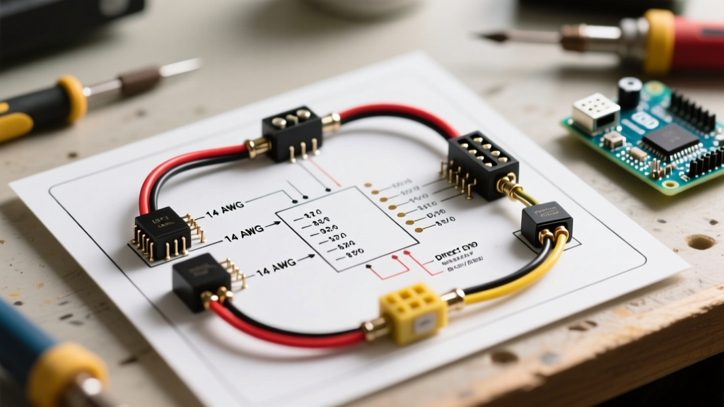
- Wire Gauge: 10 AWG copper. Use 10/3 NM-B (Romex) for older 3-wire retrofits (where legally permitted) or 10/4 NM-B for modern 4-wire setups. In 2026, 10/4 NM-B costs approximately $1.65 to $1.90 per linear foot.
- Receptacle: NEMA 14-30R (4-prong, 30-amp, 125/250V).
Pro-Tip: If you are installing a Hotpoint gas dryer (e.g., model HTX24GASKWS), it only requires a standard 120V, 15-amp or 20-amp dedicated circuit (NEMA 5-15R) to power the drum motor and igniter controls. The wiring diagram for gas models focuses on the 120V control board and gas valve solenoids, not a 240V terminal block.
Decoding the Wiring Diagram for Hotpoint Dryer Models
Locating and understanding the wiring diagram for Hotpoint dryer units is critical for troubleshooting and verifying your power cord connection. You can typically find the schematic folded inside the console panel, taped to the back of the rear access cover, or printed inside the user manual. If you need a digital replacement, the GE Appliances support portal (Hotpoint's parent company) provides free PDF schematics using your exact model number.
Key Schematic Symbols to Identify
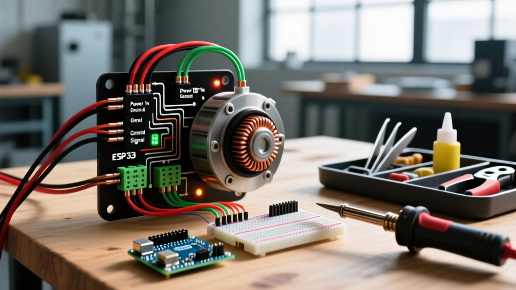
When reviewing the diagram, focus on the power entry section. You will see the following designations:
- L1 and L2: The two 120V hot legs that combine to provide 240V for the heating element.
- N (Neutral): The return path for 120V components (timer, motor, control board).
- G (Ground): The safety earth ground connected directly to the dryer's metal chassis.
- Thermal Fuse & Cycling Thermostat: Wired in series with the heating element on the L1 or L2 leg to prevent overheating.
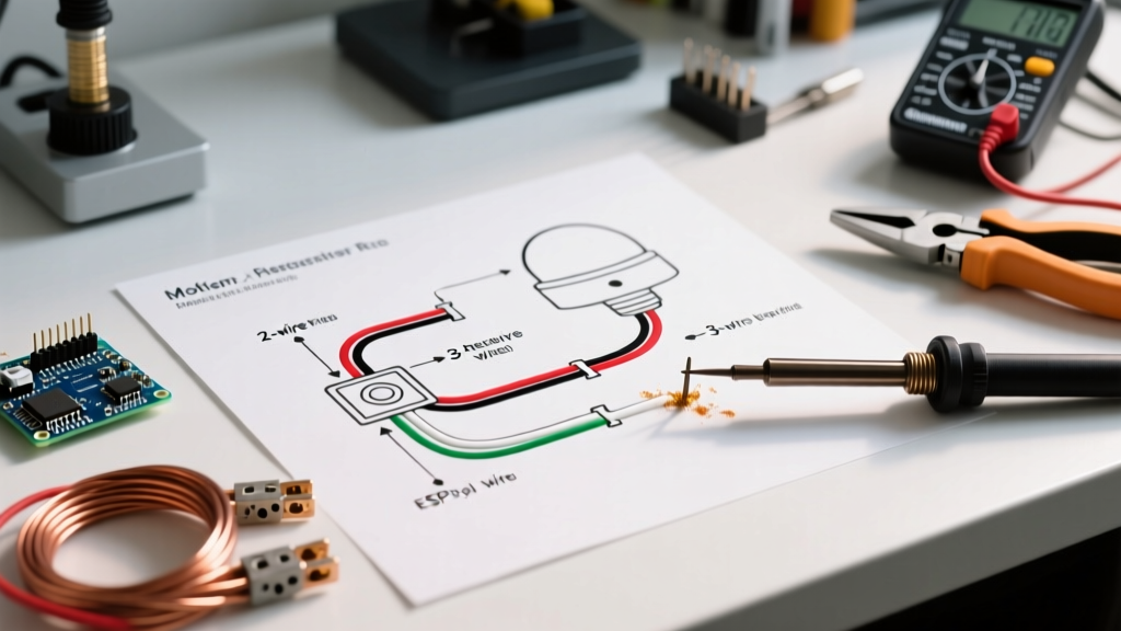
3-Prong vs. 4-Prong Power Cord Configuration
One of the most common points of confusion during installation is matching the power cord to the receptacle. The Electrical Safety Foundation International (ESFI) strongly recommends upgrading any 3-prong receptacles to 4-prong to eliminate shock hazards caused by bonded neutrals. Below is a comparison to help you plan your purchase.
| Feature | 3-Prong Cord (NEMA 10-30) | 4-Prong Cord (NEMA 14-30) |
|---|---|---|
| Wire Count | 3 Wires (Hot, Hot, Neutral) | 4 Wires (Hot, Hot, Neutral, Ground) |
| Neutral/Ground Bond | Bonded at the dryer terminal block via a metal strap. | Separated. Ground goes to chassis; neutral goes to terminal block. |
| 2026 NEC Compliance | Only permitted in pre-1996 existing homes (no new installs). | Mandatory for all new construction and major renovations. |
| Average Cord Cost | $22 - $28 | $25 - $35 |
Step-by-Step Terminal Block Wiring (4-Prong Setup)
When wiring a 4-prong cord to a Hotpoint electric dryer, the physical connection at the terminal block must be flawless. Follow these steps to ensure a safe connection:
- Remove the Bonding Strap: Locate the metal bonding strap or wire connecting the center neutral terminal to the dryer chassis. Remove it entirely. If you leave this in place on a 4-prong setup, you will create a parallel neutral path, which is a severe shock and fire hazard.
- Connect the Ground (Green): Attach the green ground wire from the cord to the external ground screw on the dryer's metal back panel. Torque to 12-15 in-lbs.
- Connect the Neutral (White): Attach the white wire to the center terminal on the block. This terminal is usually marked with 'N' or 'W' or features a silver-colored screw.
- Connect the Hot Legs (Black and Red): Attach the black wire to the left terminal (L1) and the red wire to the right terminal (L2). Note: Swapping L1 and L2 will not damage the dryer, as the 240V heating element is non-polarized, but maintaining standard color-coding is best practice.
- Secure the Strain Relief: Feed the cord through the bottom knockout hole and tighten the strain relief clamp. This prevents the wires from pulling loose from the terminal block if the dryer is moved.
Common Installation Mistakes and Failure Modes
Even experienced DIYers make mistakes when interpreting appliance schematics. Here are the most frequent failure modes associated with improper Hotpoint dryer wiring:
1. The 'Lost Neutral' Catastrophe
If the center neutral wire on the terminal block is not tightened to the proper torque (12-15 in-lbs), it can vibrate loose during the spin cycle. When the neutral is lost, the 120V motor and timer circuits attempt to complete their path through the 240V heating element. The motor receives a fraction of the required voltage, stalls, and the excessive current blows the thermal fuse. Always tug-test your terminal connections after tightening.
2. Using Aluminum Wire Without Proper Lugs
While copper is the standard, some older homes or budget builds use 10 AWG aluminum wire. If your home is wired with aluminum, you must use a receptacle rated for AL/CU (Aluminum/Copper) and apply an anti-oxidant compound (like Noalox) to the connections. Connecting aluminum wire to a standard copper-only terminal block will result in galvanic corrosion, high resistance, and eventual melting of the block.
3. Undersized Breaker Misconceptions
Some homeowners mistakenly believe that installing a 20-amp breaker for a 30-amp dryer circuit is 'safer.' In reality, the dryer's heating element draws roughly 22 to 24 amps continuously. A 20-amp breaker will trip constantly under load, and the repeated thermal stress of tripping and resetting will degrade the breaker's internal bimetallic strip, leading to premature failure.
Testing and Commissioning Your Installation
Before plugging the dryer in and pushing it against the wall, you must verify the receptacle's output using a digital multimeter. Set your multimeter to AC Voltage (V~) and perform the following checks at the NEMA 14-30R receptacle:
- L1 to L2 (Hot to Hot): Should read between 235V and 245V.
- L1 to Neutral: Should read between 118V and 122V.
- L2 to Neutral: Should read between 118V and 122V.
- Neutral to Ground: Should read less than 2V (ideally 0V).
If your Neutral-to-Ground reading is high (e.g., 5V or more), you have a floating neutral or a poor ground connection back at the main service panel. Do not plug in the dryer until this is resolved. Once the voltage checks out, plug in the dryer, run a timed dry cycle on 'Air Fluff' (no heat) for 10 minutes to verify the drum motor rotation, and then switch to 'Normal Dry' to confirm the 240V heating element engages properly.