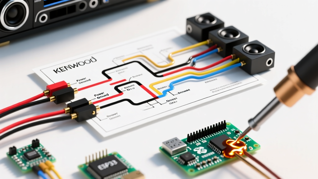

Decoding the Wiring Diagram for a Kenwood Car Stereo
Installing or repairing an aftermarket head unit requires more than just matching colors; it demands a fundamental understanding of the electrical pathways. When you are troubleshooting a wiring diagram for a Kenwood car stereo, you are essentially looking at a roadmap of the Consumer Technology Association (CTA) standard 12V DC wiring color codes, combined with Kenwood’s proprietary control wires. Whether you are working with a budget-friendly digital media receiver like the Kenwood KMM-BT328 (typically around $110) or a premium double-DIN unit like the eXcelon DDX9907XR (roughly $650), the foundational power and speaker pinouts remain remarkably consistent. This guide will walk you through advanced troubleshooting techniques using the diagram, helping you isolate power failures, memory bugs, and audio distortion without guessing.
The Anatomy of a Kenwood Stereo Wiring Harness
Before probing with a multimeter, you must understand the standard aftermarket harness (such as the Metra 70-1004 or Scosche HNN04B) that interfaces with your vehicle's factory plug. According to the Consumer Technology Association standards, 12V automotive wiring follows a strict color-code matrix. Below is the critical power and control breakdown you will find on your Kenwood wiring diagram.
| Wire Color | Function | Voltage / State | Common Troubleshooting Note |
|---|---|---|---|
| Yellow | Constant 12V (Battery) | 12.0V - 12.6V (Always On) | Supplies memory for presets and clock. If swapped with Red, unit loses memory when car is off. |
| Red | Switched 12V (Ignition) | 12.0V - 14.4V (ACC/Run) | Turns the unit on/off with the key. Must be on a fuse-protected ignition circuit. |
| Black | Chassis Ground | 0V (Reference) | Must connect to bare, unpainted chassis metal. Never use a factory ground wire. |
| Blue/White | System Remote Control | +12V Output (When On) | Triggers external amplifiers. Active in ALL source modes (BT, USB, FM). |
| Blue (Solid) | Power Antenna | +12V Output (Tuner Only) | Only outputs +12V when AM/FM radio is selected. Do not use for amp turn-on. |
| Orange/White | Illumination / Dimmer | +12V (Headlights On) | Dims the display. Some Kenwood models use Brown; always verify the specific manual. |
Top 4 Kenwood Stereo Failures (And How the Diagram Solves Them)
When a head unit malfunctions, the issue is rarely a defective radio; it is almost always a harness misconfiguration. Here is how to use your wiring diagram to diagnose the four most common installation failures.
1. The "Memory Loss" Bug (Red vs. Yellow Swap)
The Symptom: Your Kenwood stereo powers on and plays audio perfectly, but every time you turn off the car and restart it, your Bluetooth pairings, EQ settings, and radio presets are erased.
The Diagram Diagnosis: This is the classic Yellow/Red wire swap. In a wiring diagram for a Kenwood car stereo, the Yellow wire is the constant battery feed (BATT), and the Red wire is the switched ignition feed (ACC). Many novice installers connect the Kenwood Yellow wire to the vehicle's switched ignition wire, and the Red wire to the constant battery wire. Because the unit still receives power to turn on, it appears to work, but the internal volatile memory chip loses power the second the key is turned off.
The Fix: Use a digital multimeter (DMM) set to DC Voltage. Probe the vehicle's harness wires against a known ground. The wire that reads 12.6V with the key completely removed must connect to the Kenwood Yellow wire. The wire that reads 0V with the key off, but 12.6V in the ACC position, must connect to the Kenwood Red wire.
2. Dead Unit: No Power or Display
The Symptom: The screen is black, and the unit does not respond to the power button or reset pinhole.
The Diagram Diagnosis: Trace the Yellow and Red wires back to the inline fuse holder. Kenwood includes a 10A or 15A blade fuse on the Yellow constant wire right near the ISO connector. If the installer pinched the wire against the metal dash chassis during the final push-in, the fuse will blow instantly to protect the head unit's internal switching power supply. Additionally, check the Black ground wire. If it is connected to a plastic trim screw or a painted surface, the circuit cannot complete.
The Fix: Replace the inline blade fuse. For the ground, remove the Black wire from the factory harness adapter, crimp on a fresh ring terminal, and bolt it directly to a structural steel cross-member behind the dash using a star washer to bite through any paint or corrosion.
3. Amplifier Won't Trigger (Blue/White Wire Confusion)
The Symptom: The Kenwood head unit works, and external amplifiers power on when listening to FM radio, but the moment you switch to Bluetooth, Apple CarPlay, or USB, the subwoofers cut out completely.
The Diagram Diagnosis: Look closely at the remote turn-on section of the wiring diagram. Kenwood provides two blue wires: Solid Blue (Power Antenna) and Blue/White Stripe (System Remote Control). The Solid Blue wire is designed to extend a motorized radio antenna, meaning it only outputs +12V when the AM/FM tuner is active. The Blue/White wire is the dedicated amplifier trigger, outputting +12V in all source modes.
The Fix: Disconnect the vehicle's amplifier turn-on wire from the Solid Blue wire and splice it exclusively to the Blue/White striped wire. As detailed in Crutchfield's comprehensive installation guide, using the correct remote wire is critical for multi-amplifier audio systems.
4. Alternator Whine and Ground Loop Isolation
The Symptom: A high-pitched whining noise that changes pitch in direct correlation with the engine's RPMs.
The Diagram Diagnosis: Alternator whine occurs when the head unit's ground reference and the amplifier's ground reference are at different electrical potentials, creating a ground loop. The RCA cables then carry this voltage differential as audio noise. While the wiring diagram shows the Black wire as ground, it does not dictate where that ground is placed.
The Fix: Ensure the Kenwood Black ground wire is as short as possible and shares the same grounding point (or a heavily sanded, electrically continuous chassis path) as the external amplifiers. Never daisy-chain the head unit ground into the vehicle's cigarette lighter ground wire, as the high current draw from the lighter circuit will introduce noise directly into the stereo's audio pre-out stage.
Step-by-Step Multimeter Troubleshooting Workflow
When diagnosing a faulty installation, do not rely on test lights; they draw current and can trigger modern vehicle CAN-bus systems to throw error codes. Use a high-impedance digital multimeter (like the Fluke 115 or an AstroAI DM6000R) and follow this exact workflow:
- Set the DMM: Turn the dial to DC Voltage (DCV) in the 20V range.
- Establish Ground: Connect the black COM probe to a verified bare metal bolt on the vehicle's chassis.
- Test Constant (Yellow): Touch the red probe to the vehicle harness wire suspected to be constant. Read should be 12.2V - 12.6V with the key out of the ignition.
- Test Switched (Red): Turn the key to the ACC position. Probe the suspected switched wire. Read should jump to 12.4V - 14.2V (depending on alternator output).
- Test Illumination (Orange/White): Turn on the vehicle's headlight switch. Probe the illumination wire; it should jump from 0V to +12V.
- Test Amp Turn-On (Blue/White): Connect the head unit temporarily. Turn the unit on and switch to Bluetooth. Probe the Blue/White wire at the harness; it must read +12V. Switch to FM; it should remain +12V.
Connection Integrity: Why T-Taps Ruin Stereo Wiring
Expert Warning: Never use scotch locks or T-taps when splicing a Kenwood wiring harness to a factory vehicle plug. T-taps rely on a small metal blade to pierce the wire insulation, which exposes the raw copper to ambient moisture and dashboard condensation. Within 12 to 18 months, oxidation will cause a voltage drop, leading to intermittent power loss and blown internal head unit fuses.
Instead, use Posi-Twist connectors (roughly $8 for a 10-pack) or traditional solder-and-heat-shrink methods. Posi-Twists provide a gas-tight, vibration-proof connection that will easily outlast the lifespan of the vehicle. If you are using a vehicle-specific wiring interface module (like an iDatalink Maestro or Axxess ASWC-1) to retain steering wheel controls, follow the module's specific wiring diagram, as these modules often require the Kenwood Blue/Yellow or Brown/White steering wheel control wires to be routed through the interface rather than directly to the vehicle harness.
Frequently Asked Questions (FAQ)
Do I need to connect the Purple/White wire on my Kenwood diagram?
The Purple/White wire is the "Mute" control wire. It is used to mute the audio when a Bluetooth call is received if you are using an external hands-free module, or when a reverse camera is engaged. On most modern Kenwood units with built-in Bluetooth, this wire is left capped and unused unless you are integrating an external GPS navigation mute trigger.
My Kenwood diagram shows a Brown wire for illumination, but my harness has Orange/White. Which is right?
Kenwood has transitioned between Brown and Orange/White for illumination/dimmer circuits over the last decade. Always defer to the specific printed wiring diagram included in your exact model's box, or check the official Kenwood US support portal for your model's PDF manual. The CTA standard dictates Orange/White, but legacy Kenwood harnesses frequently used Brown.
Can I wire the Kenwood Yellow and Red wires together to a single constant 12V source?
Technically, yes, the radio will turn on and retain memory. However, this means the stereo will never turn off, drawing a continuous 1A to 2A standby current. If your vehicle sits for more than a few days, this parasitic draw will completely drain your car battery. Always separate them according to the diagram.