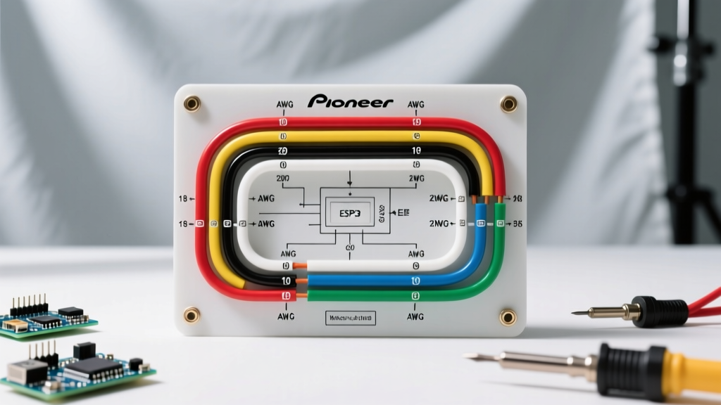

Decoding the Standard Pioneer Stereo Wiring Diagram
Installing an aftermarket head unit like the flagship Pioneer DMH-WT6000NEX or the budget-friendly MVH-S322BT requires more than just matching wire colors. While Pioneer adheres to the Consumer Technology Association (CTA) standard color codes, misinterpreting the wiring diagram for Pioneer stereo systems—specifically regarding wire gauge and striped versus solid wires—remains the leading cause of blown fuses, dimmer circuit failures, and amplifier clipping. In 2026, with modern NEX units drawing more current to power high-resolution displays and built-in DSPs, understanding both the color code and the American Wire Gauge (AWG) requirements is non-negotiable.
The Anatomy of the Pioneer 16-Pin Harness
Most aftermarket Pioneer stereos utilize a standardized 16-pin ISO/CTA connector. Before cutting into your vehicle's factory harness, you must understand the specific pinout and current limits of this connector. According to Pioneer Electronics official documentation, the 16-pin harness is divided into power/ground, amplifier control, illumination, and speaker outputs.
The CTA/EIA Color Code & Gauge Reference Chart
The Consumer Technology Association (CTA) established the universal color code for car audio to ensure cross-brand compatibility. Below is the definitive reference chart for Pioneer head units, including the factory wire gauge and the recommended upgrade gauge for extended runs.
| Wire Color | Function | Factory Gauge | Recommended Upgrade | Max Current / Notes |
|---|---|---|---|---|
| Yellow | Constant 12V (Battery) | 18 AWG | 12 AWG - 14 AWG | 15A-20A. Keeps memory alive. Upgrade to prevent voltage drop. |
| Red | Switched 12V (Ignition) | 18 AWG | 14 AWG | 10A-15A. Triggers head unit turn-on. |
| Black | Chassis Ground | 18 AWG | 12 AWG - 14 AWG | Must match Yellow wire gauge. Ground to bare metal. |
| Blue / White Stripe | Amplifier Remote Turn-On | 18 AWG | 18 AWG | Max 300mA. Do not wire directly to high-draw amp remote. |
| Orange | Illumination (On/Off) | 20 AWG | N/A | Simple 12V trigger when headlights turn on. |
| Orange / White Stripe | Illumination Dimmer (Variable) | 20 AWG | N/A | Variable voltage (12V to 0V). Use with caution on CAN-bus. |
| White / White-Black | Front Left Speaker (+/-) | 18 AWG | 16 AWG OFC | Standard speaker run. Use 14 AWG for high-power components. |
| Gray / Gray-Black | Front Right Speaker (+/-) | 18 AWG | 16 AWG OFC | Standard speaker run. |
| Green / Green-Black | Rear Left Speaker (+/-) | 18 AWG | 16 AWG OFC | Standard speaker run. |
| Purple / Purple-Black | Rear Right Speaker (+/-) | 18 AWG | 16 AWG OFC | Standard speaker run. |
Wire Gauge Selection: Matching AWG to Your Pioneer Setup
One of the most critical errors DIY installers make is relying on the thin 18 AWG wires pre-installed on the Pioneer pigtail. While 18 AWG is sufficient for the short 12-inch run from the connector to the radio's internal circuit board, extending these wires across the dashboard or directly to the battery requires a gauge upgrade.
Power and Ground: The Voltage Drop Problem
Modern multimedia receivers like the Pioneer AVH-W4500NEX can draw up to 15 amps continuously when the screen is at maximum brightness and the internal amplifier is driving four speakers. According to the NFPA 70 National Electrical Code guidelines for DC automotive applications, pushing 15A through 18 AWG wire over a distance of 10 feet will result in a severe voltage drop. If the voltage at the head unit drops below 11.5V during heavy bass transients, the NEX unit will hard-reboot to protect its memory.
- The Fix: Cut the Yellow, Red, and Black wires close to the Pioneer plug. Solder and heat-shrink 14 AWG or 12 AWG Oxygen-Free Copper (OFC) wire for the extension to the fuse box and chassis ground.
- Cost Reality: High-quality 12 AWG OFC wire costs approximately $1.20 to $1.80 per foot in 2026. Avoid Copper-Clad Aluminum (CCA) wire, which is often deceptively marketed online; CCA has 40% higher resistance and requires you to jump up two full AWG sizes to match OFC performance.
Speaker Wire: 16 AWG vs. 18 AWG
Pioneer's internal amplifier outputs roughly 14W RMS per channel (despite the box claiming 50W x 4). For standard 6.5-inch coaxial speakers, 16 AWG OFC speaker wire is the optimal choice. It provides less than 1% signal loss over standard 15-foot door runs. If you are bypassing the internal amp and using the Pioneer's 4V RCA preouts to feed an external 5-channel amplifier, you do not need to wire the speaker-level outputs at all.
CRITICAL WARNING: The Remote Turn-On Wire Limit
The Blue/White wire on your Pioneer diagram is rated for a maximum of 300mA. If you are wiring multiple amplifiers, a DSP, and a line driver, the combined remote current draw will exceed 300mA, frying the head unit's internal switching transistor. Always use a 12V automotive relay (costing about $5) triggered by the Blue/White wire to switch the heavy current directly from the battery for your amplifier rack.
Step-by-Step: Adapting Factory Harnesses to Pioneer Diagrams
In modern vehicles, you rarely wire the Pioneer diagram directly to the car's factory wires. Vehicles from 2015 onward utilize CAN-bus data networks for ignition sensing and chime routing. You will need a vehicle-specific wiring harness adapter.
Common 2026 Harness Adapters & Pricing
- PAC RP4-CH11 (Chrysler/Jeep/Dodge): Priced around $59.99 - $69.99. This module retains the factory steering wheel controls and amplifier turn-on. Diagram Change: You only wire the Pioneer's Yellow, Red, Black, and 4 speaker pairs to the PAC harness. The PAC module generates the 12V switched signal from the CAN-bus.
- Metra AXXESS XSVI-2104-NAV (Ford/Lincoln): Priced around $49.99. Retains factory backup camera and SYNC audio chimes. Diagram Change: The Pioneer Orange/White dimmer wire is left disconnected, as the Metra module handles screen dimming via data.
- Metra 70-1761 (Honda/Acura - Base Audio): Priced around $12.99. A simple plug-and-play analog harness. Diagram Change: Direct 1-to-1 color matching between the Pioneer pigtail and the Metra harness.
Troubleshooting Common Wiring Diagram Misinterpretations
Even seasoned installers occasionally misread the subtle differences in the Pioneer wiring diagram. Here are the most common edge cases and how to resolve them.
Edge Case 1: Solid Blue vs. Blue/White Stripe
Older Pioneer diagrams feature a solid Blue wire (Power Antenna) and a Blue/White stripe wire (System Remote). Never use the solid Blue wire to turn on an amplifier. The solid Blue wire outputs 12V only when the AM/FM radio tuner is active. The moment you switch to Bluetooth, USB, or Apple CarPlay, the solid Blue wire drops to 0V, turning off your amplifiers and causing a loud, damaging 'pop' through your subwoofers. Always use the Blue/White stripe wire, which remains at 12V as long as the head unit is powered on.
Edge Case 2: The Illumination Wire Trap
Pioneer provides both an Orange wire (Illumination On/Off) and an Orange/White wire (Dimmer). If your vehicle uses a variable voltage dimmer switch (where the dashboard lights smoothly fade from 12V down to 4V), connecting the Pioneer Orange/White wire to this circuit can cause erratic screen behavior or damage the head unit's dimmer resistor. If your vehicle has a CAN-bus dimmer, simply tape off both Orange wires and control the screen brightness via the Pioneer settings menu.
Frequently Asked Questions
Can I use the RCA ground shields as a chassis ground?
No. The RCA cables on the back of a Pioneer NEX unit are tied to the audio signal ground, not the main power ground. Using RCA shields as a chassis ground will introduce severe alternator whine into your audio system. Always use the dedicated 18 AWG Black wire on the main harness for the primary ground.
What happens if I swap the Yellow and Red wires?
If you wire Constant 12V to the Red (Switched) wire, and Switched 12V to the Yellow (Constant) wire, your Pioneer stereo will turn on and off correctly, but it will lose all saved settings (EQ, clock, paired Bluetooth devices, and radio presets) every time you turn off the car. The Yellow wire must always have uninterrupted battery power to maintain the volatile memory.
Do I need to connect the Black/White wire (Phone Mute)?
On most modern Pioneer diagrams, the Black/White or Mute wire is a legacy feature designed for external navigation modules or Bluetooth kits that are now integrated directly into the head unit. Unless you are installing an external radar detector with a specific mute trigger, leave this wire capped and isolated.