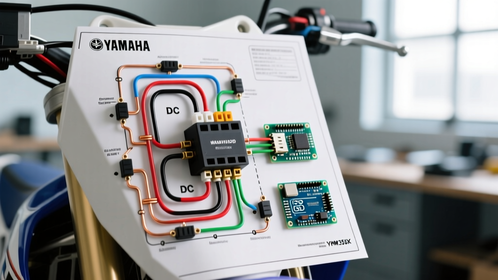

Understanding the YFM350X Electrical Architecture
The Yamaha Warrior 350 (YFM350X) remains one of the most reliable and heavily modified sport-utility ATVs on the trails. While its carbureted 348cc engine is mechanically straightforward, its 12V DC electrical system requires careful management, especially when owners begin adding modern accessories. Whether you are restoring a barn-find or rigging a custom plow setup, interpreting the electrical yamaha warrior 350 wiring diagram is the critical first step in designing a safe, robust DC fuse and breaker panel.
Unlike residential AC breaker panels, the Warrior 350 utilizes a 12V DC fuse block and a main fusible link to protect its low-voltage, high-current environment. In 2026, with the proliferation of high-efficiency LED light bars, 12V winches, and heated grips, the stock Yamaha fuse panel is often pushed to its absolute limits. This guide bridges the gap between the OEM wiring schematic and practical DC panel upgrades, focusing on circuit protection, wire gauge selection, and thermal breaker integration.
Decoding the Electrical Yamaha Warrior 350 Wiring Diagram
When you trace the electrical yamaha warrior 350 wiring diagram, power distribution originates at the 12V battery (typically a YB12A-A or YTX19L-BS equivalent). The positive terminal feeds directly into a main 30A fusible link before reaching the ignition switch and the primary fuse box. The stator generates 3-phase AC power, which is converted to roughly 14.2V DC by the regulator/rectifier (RR) to charge the battery and supply the DC bus.
The stock fuse panel is a simple 4-to-5 slot ATC/ATO blade fuse block. It protects the headlight, taillight, ignition/CDI, and a single auxiliary circuit. Because the Warrior 350's stator output is relatively modest (peaking around 180W-200W at 5000 RPM), overloading the stock panel with aftermarket accessories will quickly result in voltage drops, melted fuse holders, or a depleted battery.
Stock Circuit Protection Matrix
Below is a breakdown of the OEM circuit protection specifications based on the factory service manual. Always verify your specific year's schematic, as minor harness revisions occurred throughout the production run.
| Circuit Function | OEM Fuse Rating | Wire Gauge (AWG) | Max Continuous Load | Common Failure Mode |
|---|---|---|---|---|
| Main Battery Feed | 30A Fusible Link | 10 AWG | 24A (80% rule) | Corrosion at battery terminal |
| Headlight (AC/DC) | 10A | 16 AWG | 8A | Melted connector due to halogen heat |
| Taillight / Brake | 10A | 18 AWG | 8A | Frayed harness near swingarm pivot |
| Ignition / CDI | 10A | 16 AWG | 8A | Short to ground on steering column |
| Auxiliary (12V Outlet) | 10A | 16 AWG | 8A | Overloaded by aftermarket accessories |
Designing an Auxiliary DC Breaker and Fuse Panel
To safely run high-draw accessories like a 2,500 lb winch or a 50-inch LED light bar, you must bypass the stock auxiliary circuit and install a dedicated auxiliary fuse panel. According to guidelines from Blue Sea Systems, any auxiliary DC panel should be fed by a dedicated heavy-gauge wire protected by a primary fuse or DC circuit breaker located within 7 inches of the battery positive terminal.
Selecting DC Breakers for High-Draw Accessories
A common mistake when modifying the Warrior 350 is using a standard automotive blade fuse for a winch circuit. Winches experience massive inrush currents (often exceeding 120A under heavy load) that will instantly blow a standard fuse or cause dangerous arcing. For inductive loads like winch motors, a thermal DC circuit breaker is mandatory. The Bussmann CB185-50 (50A thermal breaker, approx. $28 in 2026) is the industry standard for light ATV winches. It handles high inrush spikes without nuisance-tripping, while still protecting the 4 AWG battery cables from melting in the event of a dead short.
For resistive or steady-state loads (like LED light bars, heated grips, or GPS units), an auxiliary blade fuse panel like the Blue Sea 5025 ST Blade (approx. $42) is ideal. It consolidates multiple accessory circuits into a single, waterproof enclosure with independent ATC fuses.
Step-by-Step Auxiliary Panel Installation Guide
Upgrading your panel requires strict adherence to NFPA 70 (National Electrical Code) principles adapted for mobile DC applications, specifically regarding wire ampacity and overcurrent protection placement.
- Disconnect and Isolate: Remove the negative battery terminal first. Tape the end to prevent accidental contact with the chassis.
- Mount the Auxiliary Panel: Secure the Blue Sea ST Blade panel in a dry, elevated location under the front plastics, away from the stator heat and steering shaft U-joints.
- Run the Main Feeder Wire: Use 10 AWG marine-grade, tinned copper wire (TX6) for the feed from the battery to the auxiliary panel. Tinned copper resists the galvanic corrosion common in off-road environments.
- Install the Primary Protection: Crimp a 40A MIDI or MEGA fuse holder directly onto the positive battery terminal ring. This protects the entire 10 AWG feeder wire.
- Integrate a Heavy-Duty Relay: To prevent parasitic draw when the ATV is off, wire a 40A Bosch-style relay (or a solid-state equivalent) inline with the panel feed. Trigger the relay coil using the Warrior's OEM ignition-switched 12V wire (typically red/white, verify with your multimeter).
- Terminate and Seal: Use adhesive-lined heat shrink terminals (not vinyl or nylon) for all connections. Apply dielectric grease to the fuse slots to prevent moisture ingress.
Common Panel Failures and Voltage Drop Diagnostics
The Yamaha Warrior 350 is notorious for developing ground-side voltage drops as the chassis ages and oxidizes. A failing circuit is rarely the fault of the fuse itself; it is usually a resistance issue at the panel bus bars or ground terminals.
According to Littelfuse automotive application notes, a properly functioning DC circuit should exhibit a total voltage drop of less than 0.1V across the fuse and bus bar under load. If your LED light bar is flickering or your winch is sluggish, perform a voltage drop test before replacing components.
Troubleshooting Flowchart: Voltage Drop Testing
- Step 1: Set your multimeter to DC Volts. Turn on the failing accessory (e.g., headlight).
- Step 2: Place the red probe on the battery positive terminal and the black probe on the input side of the fuse panel. A reading above 0.2V indicates high resistance in the positive feeder wire or main fusible link.
- Step 3: Place the red probe on the output side of the fuse and the black probe on the accessory's positive terminal. A reading above 0.1V indicates undersized wire or a corroded inline connector.
- Step 4: Test the ground path. Place the red probe on the accessory's ground wire and the black probe directly on the battery negative terminal. Any reading above 0.1V means the chassis ground point is corroded. Sand the frame down to bare metal and apply a zinc-rich primer after bolting the ground ring terminal.
Wire Gauge Selection for 12V DC Panels
Selecting the correct wire gauge is paramount when extending the electrical yamaha warrior 350 wiring diagram to a new breaker panel. Unlike 120V AC household wiring, 12V DC systems suffer from severe voltage drop over distance. A wire that is perfectly safe for a 10-foot run in a house may cause a 20% voltage drop on a 15-foot run on an ATV, leading to dim lights and overheated wires.
| Max Current (Amps) | Wire Gauge (AWG) | Max Fuse/Breaker Size | Typical ATV Application |
|---|---|---|---|
| 5A - 7A | 18 AWG | 7.5A | Taillights, GPS, Dash Indicators |
| 10A - 15A | 14 AWG | 15A | LED Light Bars, Heated Grips |
| 20A - 30A | 10 AWG | 30A | Main Panel Feeder, Horn Relay |
| 50A+ | 4 AWG or 2 AWG | 50A - 70A Breaker | Winch Motor, Starter Solenoid |
Final Thoughts on Circuit Protection
Upgrading the fuse and breaker panel on your Yamaha Warrior 350 transforms it from a basic 1990s electrical architecture into a modern, reliable platform capable of handling today's demanding off-road accessories. By strictly following the OEM wiring diagram for your trigger sources, utilizing thermal breakers for inductive loads, and adhering to proper DC wire gauge sizing, you ensure that your machine remains protected against shorts, fires, and parasitic drains. Always verify your specific stator output with a multimeter before adding continuous loads that exceed 150W to prevent draining the battery at idle.