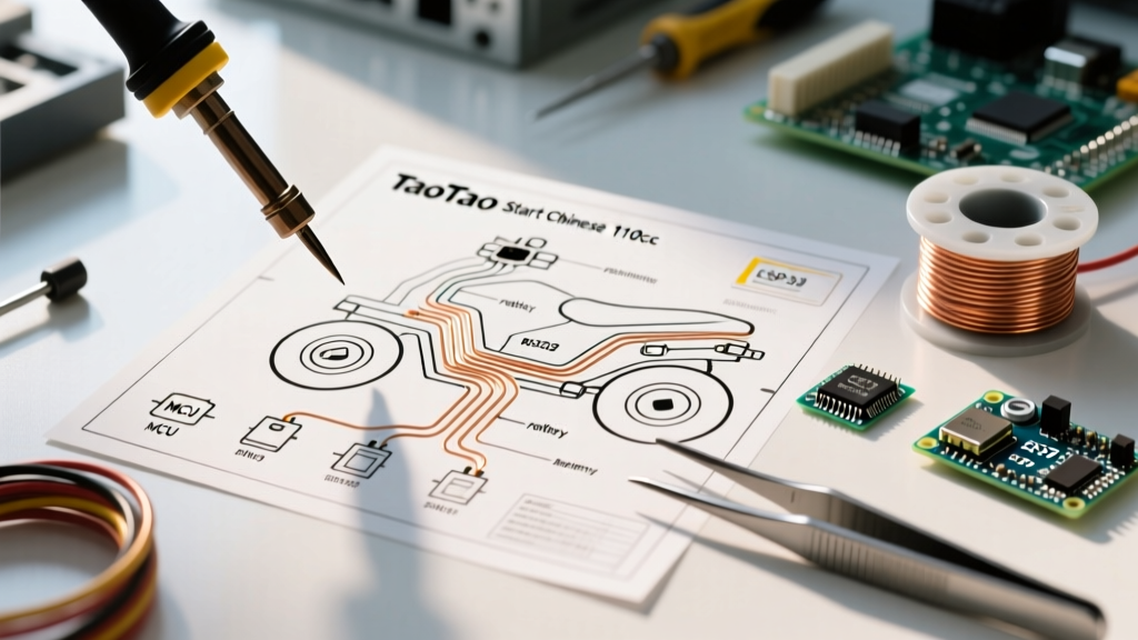

Introduction to TaoTao 110cc Electrical Systems
Owning a Chinese-manufactured 110cc ATV, such as the popular TaoTao ATA-110D, Boulder B1, or T-Force 110, is an excellent entry point into off-road riding. However, the electrical systems on these machines are notorious for causing headaches. Unlike major domestic or Japanese brands that adhere to strict, standardized wiring schematics, TaoTao and similar manufacturers often utilize generic, mass-produced wiring harnesses. This results in inconsistent wire color coding, undersized gauge wiring for high-draw circuits, and vulnerable connector pins that corrode quickly when exposed to mud and moisture.
Whether you are replacing a melted harness, upgrading to a heavier-duty starter solenoid, or simply trying to figure out why your electric start is clicking without engaging, understanding the underlying circuit logic is mandatory. This step-by-step walkthrough decodes the TaoTao electric start Chinese 110cc ATV wiring diagram, providing actionable diagnostics and exact pinouts to get your quad running reliably.
The Golden Rule: Wire Colors Are Merely a Suggestion
Before touching a single wire, you must accept the most critical rule of Chinese ATV repair: never trust wire colors blindly. While Japanese manufacturers follow strict color codes (e.g., Honda's green for ground, black/white for kill), TaoTao harnesses are assembled from whatever bulk wire spools are available at the factory on a given day. You might find a green wire serving as a 12V power feed on one batch, and a ground on the next.
Always verify circuit continuity and voltage with a digital multimeter. Relying solely on a generic TaoTao wiring diagram's color legend is the fastest way to short-circuit your stator or fry your CDI unit.
According to the SAE International J1128 standard for low-tension primary cables, specific colors are designated for specific battery cable functions, but aftermarket import harnesses rarely comply. You must trace the physical path of the wire from component to component.
Core Component Reference Matrix
Below is a breakdown of the primary electrical components in the TaoTao 110cc electric start circuit, including their expected functions and the reality of their wire colors in the field.
| Component | Function | Expected Color | Common TaoTao Reality | Wire Gauge |
|---|---|---|---|---|
| Main Battery Feed | Supplies 12V DC to harness | Red | Red, Faded Pink, or Orange | 12-14 AWG |
| Chassis Ground | Completes circuit to frame | Black or Green | Black, Green, or Bare Copper | 14-16 AWG |
| Kill Switch | Grounds CDI to stop spark | Black/White | Solid Black or Black/Yellow | 18 AWG |
| Stator Trigger | Sends timing pulse to CDI | Blue/White | Pink, Pink/White, or Blue | 20-22 AWG |
| Stator Lighting Coil | AC Power for lights/charging | Yellow | Yellow or White | 16-18 AWG |
Step-by-Step Wiring Walkthrough
Step 1: Battery, Main Fuse, and Starter Solenoid
The electric start circuit begins at the 12V 4Ah or 5Ah Sealed Lead Acid (SLA) battery. From the positive terminal, a heavy-gauge red wire routes to an inline main fuse (typically 15A or 20A). Diagnostic Tip: If your ATV is completely dead, check this fuse first. It is usually housed in a cheap, rubber-inline cylinder near the battery box that is prone to water ingress.
From the fuse, power splits. One branch feeds the ignition switch, while the heavy-gauge branch routes directly to the large terminal on the starter solenoid (relay). The solenoid acts as a heavy-duty switch. It has two large posts (Battery In, Starter Motor Out) and two small spade terminals for the trigger circuit.
- Large Post 1: Constant 12V from the battery.
- Large Post 2: Switched 12V out to the starter motor bendix.
- Small Terminal 1: 12V trigger from the start button (only hot when button is pressed).
- Small Terminal 2: Ground (often internally grounded through the mounting bracket or via a dedicated black wire to the frame).
Edge Case Failure: If you turn the key and hear a single loud 'clack' but the engine does not turn over, the solenoid is engaging, but the internal copper contacts may be pitted, or the starter motor is drawing too many amps due to a failing bendix gear. Use a multimeter to check for voltage drop across the large posts while pressing the start button. A drop greater than 0.5V indicates a failing solenoid.
Step 2: Start Button and Brake Interlock Circuit
TaoTao 110cc ATVs feature a mandatory safety interlock: the engine will only crank if the brake lever is depressed. The wiring for this circuit routes 12V from the ignition switch, through the brake light switch, and then to the handlebar-mounted start button.
- Turn the ignition key to the 'ON' position. Verify 12V at the input wire of the brake light switch using the DC Volts setting on your multimeter.
- Squeeze the brake lever. Verify 12V exits the brake switch and travels to the start button.
- Press the start button. Verify 12V exits the start button and reaches the small trigger terminal on the starter solenoid.
If the brake light illuminates but the starter won't engage, the brake switch is likely a dual-circuit switch where the start-interlock half has failed internally, a very common issue on $12 replacement switches.
Step 3: Stator, Regulator/Rectifier, and CDI Pinout
The ignition and charging systems are the heart of the ATV. The stator (mounted behind the left-side engine cover) generates raw AC voltage. This voltage is sent to the Regulator/Rectifier (R/R), which converts it to a regulated 12V-14V DC to charge the battery and power the lights.
The 4-Pin Regulator/Rectifier:
- Yellow (x2): Connects to the stator's AC lighting coils. Polarity does not matter.
- Red: Regulated 12V DC output to the battery and harness.
- Green: Chassis ground. Crucial: If this ground is poor, the R/R cannot regulate voltage, and you will see 18V+ at the battery, boiling the acid and blowing headlight bulbs.
The 5-Pin CDI (Capacitor Discharge Ignition):
TaoTao 110cc horizontal engines typically use a DC-CDI. The pinout is where most DIYers make fatal errors, as Chinese CDIs often swap the ground and kill pins compared to Japanese GY6 equivalents.
- Pin 1 (Black/Yellow): High voltage output to the ignition coil.
- Pin 2 (Black/White or Solid Black): Kill switch circuit. When grounded, it stops the spark.
- Pin 3 (Pink/White or Blue/White): Stator trigger/pickup coil signal.
- Pin 4 (Green): Chassis ground.
- Pin 5 (Red or Black): 12V DC power input from the ignition switch.
Advanced Troubleshooting and Edge Cases
When diagnosing a no-spark or no-crank condition on a TaoTao 110cc, systematic isolation is required. Here are the most frequent edge cases encountered in the shop:
The 'Welded Solenoid' Runaway
If your ATV starter continues to crank even after you release the start button or turn the key off, the internal contacts of the starter solenoid have physically welded together due to arcing. Immediate Action: Disconnect the positive battery terminal immediately to prevent the starter motor from catching fire or destroying the engine's ring gear. Replace the solenoid and inspect the starter motor for excessive draw.
The Phantom Kill Switch Ground
If you have 12V at the CDI, a strong blue spark at the plug, and good compression, but the engine backfires through the carburetor without starting, your ignition timing is off. On TaoTao quads, this is almost always caused by a frayed Black/White kill wire rubbing against the frame under the steering stem, creating a partial ground that weakens the CDI's capacitive discharge just enough to retard the spark.
Stator Resistance Testing
Before replacing a $35 CDI, test the stator. Unplug the stator harness connector. Set your multimeter to Ohms (Ω). Measure between the Pink/White trigger wire and the Green ground wire. You should see a resistance between 110 and 180 ohms. If it reads 'OL' (Open Loop), the internal pickup coil is broken, and the entire stator must be replaced.
Essential Tools and Preventative Maintenance
Working on import ATV wiring requires specific tools to ensure long-term reliability. Standard electrical tape is insufficient for the high-vibration, high-moisture environment of an ATV chassis.
- Wire Piercing Probes: Use these to test for voltage without stripping back the wire insulation, which invites corrosion.
- Dielectric Grease: Pack every multi-pin plastic connector (especially the CDI and Stator plugs) with Permatex 22058 dielectric grease to prevent water intrusion and galvanic corrosion.
- Heat Shrink Tubing: Use adhesive-lined, dual-wall heat shrink (3M or equivalent) for all soldered splices. The inner adhesive melts and seals the wire strands against moisture.
- Loom and Zip Ties: Reroute wiring away from the exhaust header and steering stem pivot points. The U.S. Consumer Product Safety Commission (CPSC) frequently notes that improperly routed wiring causing sudden electrical failure or shorts can lead to loss of vehicle control or fire hazards.
Conclusion
Mastering the TaoTao electric start Chinese 110cc ATV wiring diagram is less about memorizing a static schematic and more about understanding the fundamental flow of 12V DC power, grounds, and signal triggers. By ignoring misleading wire colors and relying on multimeter-verified continuity, you can troubleshoot, repair, and upgrade your ATV's electrical system with confidence. Whether you are swapping a $12 regulator/rectifier or tracing a parasitic draw, a methodical, step-by-step approach will save you hours of frustration and prevent costly component damage.