
The CD6 Architecture: Why the Wiring Diagram for Ford Explorer Matters
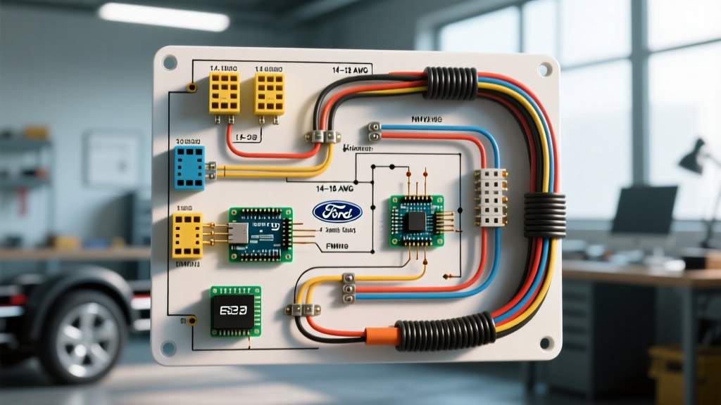
The 6th-generation Ford Explorer (2020–2026), built on the CD6 rear-wheel-drive/unibody architecture, utilizes a highly sensitive multiplexed CAN bus electrical system. Unlike older vehicles where you could safely splice into tail light circuits using standard scotch locks, modern Explorers employ a dedicated Trailer Module (TRM) and a Body Control Module (BCM) that actively monitor current draw down to the milliamp. If you attempt a trailer lighting upfit without consulting a precise wiring diagram for Ford Explorer models, the BCM will instantly detect the abnormal resistance, shut down the circuit to prevent a fire, and log a hard Diagnostic Trouble Code (DTC). Replacing a fried BCM on a 2024 Explorer costs between $1,200 and $1,800, plus mandatory dealership programming.
This guide provides a safety-first, code-compliant approach to reading and executing Ford Explorer trailer wiring diagrams, ensuring your upfit meets both SAE and federal DOT standards.
Decoding the Factory 7-Pin Harness and TRM Integration
When you pull the factory wiring diagram for Ford Explorer tow packages, you will notice the 7-way RV blade connector is not wired directly to the BCM. Instead, it routes through the TRM, typically located behind the passenger-side rear quarter panel trim. The TRM acts as a galvanic isolator and power distribution node.
| Pin Position | Function | Wire Color (Standard 7-Way) | Explorer TRM Fuse Rating | Wire Gauge Requirement |
|---|---|---|---|---|
| 1 (Ground) | White (Ground) | White | N/A (Chassis Ground) | 10 AWG (Min) |
| 2 (Tail/Running) | Brown (Tail Lights) | Brown | 15A (TRM Internal) | 16 AWG |
| 3 (Left Stop/Turn) | Yellow (Left) | Yellow | 20A (TRM Internal) | 14 AWG |
| 4 (Right Stop/Turn) | Green (Right) | Green | 20A (TRM Internal) | 14 AWG |
| 5 (Electric Brakes) | Blue (Brakes) | Blue | 30A (BJB Fuse 27) | 10 AWG |
| 6 (12V Auxiliary) | Black (12V Power) | Black/Red | 30A (BJB Fuse 12) | 10 AWG |
| 7 (Reverse Lights) | Purple (Aux/Reverse) | Purple | 15A (TRM Internal) | 16 AWG |
SAE J1128 and FMVSS 108: The Compliance Baseline
Safety and code compliance in automotive wiring are governed by strict industry and federal standards. When sourcing wire and lighting components for your Explorer trailer upfit, you must adhere to the following:
- SAE J1128 (Low Tension Primary Cable): According to the SAE J1128 standard, any wire routed under the chassis or exposed to engine bay temperatures must be cross-linked polyethylene (GXL or TXL). GXL wire is rated for 125°C and features a thin wall that resists abrasion and chemical degradation from road salts. Never use standard PVC THHN wire for automotive trailer harnesses; it becomes brittle at -20°C and melts near exhaust components.
- FMVSS 108 (Lamps, Reflective Devices, and Associated Equipment): The Federal Motor Vehicle Safety Standard 108 dictates that trailer stop lamps must illuminate within a specific candela range and latency. If your DIY wiring introduces excessive voltage drop, the trailer brakes lights may glow dimly, failing federal safety inspection and creating a severe rear-end collision hazard.
Safety Warning: Never bypass the factory Trailer Module to wire trailer lights directly to the Explorer's rear tail light pigtails. The CD6 platform uses PWM (Pulse Width Modulation) for certain lighting circuits to save energy. Direct splicing will result in strobing trailer lights and immediate CAN bus network faults.
Wire Gauge Sizing and Voltage Drop Mitigation
A common failure mode in DIY trailer wiring is undersizing the 12V auxiliary and electric brake circuits. The Explorer's TRM is located roughly 15 feet from the rear hitch. When you add a 25-foot trailer tongue and axle runs, your total circuit length for the electric brakes can easily exceed 50 feet (round trip).
Calculating Voltage Drop for the 12V Auxiliary Circuit
Suppose you are wiring a 12V compressor fridge on your trailer that draws 12 Amps continuously. Using the standard voltage drop formula: VD = (2 x K x I x L) / CM
- K (Copper resistance constant) = 12.9
- I (Current) = 12A
- L (Length one-way) = 40 feet (Explorer TRM to trailer fridge)
- CM (Circular Mils for 10 AWG) = 10,380
Calculation: (2 x 12.9 x 12 x 40) / 10,380 = 1.19 Volts dropped.
Your fridge will receive 10.81V, which is generally acceptable. However, if you mistakenly used 14 AWG wire (CM = 4,110), the voltage drop would be 3.01V, delivering only 8.99V to the fridge, causing the compressor to stall, overheat, and potentially draw locked-rotor amperage that could melt the harness. Always use 10 AWG GXL wire for the Black (12V) and Blue (Brake) pins on the 7-way connector.
Step-by-Step: Installing an Aftermarket Isolation Module Safely
If your Explorer did not come with the factory Class III Tow Package, you lack the TRM. To add a 4-pin or 7-pin connector safely without triggering BCM DTCs like B1433 (Left Stop/Turn Circuit Failure), you must install a powered isolation module, such as the Tekonsha 119190KIT or Curt 56385 (retailing between $65 and $85). These modules draw power directly from the battery and use the vehicle's tail light signals only as low-current switching triggers.
- Disconnect the Battery: Drop the negative terminal on the Explorer's 12V AGM battery. Wait 5 minutes for the CAN bus modules to enter sleep mode.
- Tap the Signals: Use a proper wiring diagram for Ford Explorer rear harness pinouts to identify the left turn, right turn, tail, and ground wires. Use T-taps only on the signal side, or preferably, use Posi-Tap connectors to avoid severing the OEM copper strands.
- Route the Heavy Power Wire: Run the included 10 AWG red power wire from the module to the battery. Route it along the factory chassis harness on the driver's side frame rail. Secure it every 12 inches using UV-rated nylon zip ties.
- Install the Mega-Fuse: Install the 30A inline fuse within 18 inches of the battery positive terminal. This complies with ABYC and SAE overcurrent protection standards, ensuring that if the power wire chafes against the frame, the fuse blows before a chassis fire starts.
- Establish a Chassis Ground: Do not ground the white wire to a painted bolt. Use a wire brush to expose bare steel on the chassis, attach a 10 AWG ring terminal using a stainless steel star washer, and coat the connection with Permatex 22058 dielectric grease to prevent galvanic corrosion.
Common Edge Cases and Troubleshooting DTCs
Even with a perfect wiring diagram for Ford Explorer upfits, environmental factors and edge cases can cause faults. Keep an OBD-II scanner capable of reading Ford-specific BCM and TRM codes handy.
- DTC B1A61 (Trailer Tow Turn/Stop Lamp Left Circuit Open): This often occurs when a trailer's LED lights draw too little current for the TRM to detect a closed circuit. The BCM thinks the bulb is blown. Fix: Install a CAN bus-compatible LED load resistor kit (usually 6-ohm, 50W) in parallel with the trailer's left turn signal.
- DTC U0231 (Lost Communication with Rain Sensing Module): Surprisingly, a short in the trailer's 7-way connector (specifically if the 12V aux pin shorts to the CAN bus pins in a damaged plug) can flood the Explorer's MS-CAN network with noise, taking down unrelated modules. Fix: Inspect the trailer plug for bent pins and use a 7-way socket cover to prevent water ingress when not towing.
- Voltage Feedback through the Brake Controller: If wiring an aftermarket proportional brake controller (like the Tekonsha Prodigy P3) under the dash, ensure the blue output wire is spliced only into the dedicated TRM brake feed wire under the driver's kick panel. Splicing it into the wrong harness can feed 12V backward into the Explorer's ABS module.
Further Authoritative References
For comprehensive vehicle-specific wiring schematics and trailer lighting FAQs, consult eTrailer's Vehicle Wiring Database, which maintains up-to-date pinout charts and TRM bypass procedures for all recent Ford SUV platforms. Always cross-reference your specific VIN's build sheet via the Ford Motorcraft service portal before cutting or splicing any wires.