
Understanding the 2-Wire Thermostat Architecture
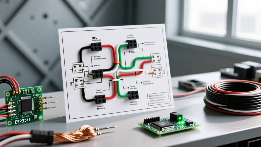
When dealing with residential HVAC systems, the wiring diagram for 2 wire thermostat configurations represents the most fundamental, single-stage heat-only control circuit. Whether you are wiring a gas furnace, an oil boiler, or a hydronic baseboard system, a 2-wire setup acts as a simple closed-loop switch. When the ambient temperature drops below the setpoint, the thermostat closes the circuit, allowing current to flow from the power source to the heating appliance's control relay.
Before touching any wires, it is critical to identify whether your system operates on low-voltage (24VAC) or line-voltage (120V/240V). Confusing the two is a common DIY error that results in destroyed control boards, blown transformers, or severe electrical shock. In 2026, the vast majority of modern forced-air and boiler systems utilize 24VAC control circuits, while line-voltage is strictly reserved for electric resistance baseboard heaters and wall fan heaters.
Low-Voltage (24V) vs. Line-Voltage (120V/240V)
To determine your system type, remove the existing thermostat cover and inspect the wires. Low-voltage wires are typically 18 AWG to 20 AWG solid copper, often bundled in a multi-conductor jacket (even if only two wires are used). Line-voltage wires are much thicker (12 AWG or 14 AWG), usually sheathed in standard Romex (NM-B) cable, and connect via wire nuts rather than screw terminals. Always verify with a True RMS multimeter, such as the Fluke 117, before proceeding.
CRITICAL SAFETY WARNING: Never assume wire color dictates voltage. While red and white are standard for 24VAC systems, previous installers may have used unconventional colors. Always kill the power at the main service panel and verify the circuit is dead using a non-contact voltage tester and a multimeter.
The Core Wiring Diagram for 2 Wire Thermostat Terminals
For a standard 24VAC heat-only system (such as a Honeywell RTH221B1021 or Emerson 1E78-140, both retailing around $16 to $24 in 2026), the wiring diagram is remarkably straightforward. The thermostat requires a power source and a switch leg to call for heat.
| Thermostat Terminal | Standard Wire Color | Function | Furnace Board Terminal |
|---|---|---|---|
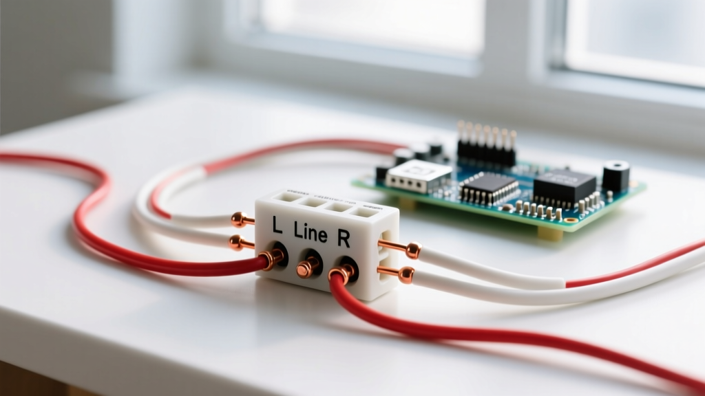
| R (or Rh) | Red | 24VAC Hot Power from Transformer | R |
| W (or W1) | White | Heat Call (Switched 24VAC Return) | W |
Note: If your thermostat has separate Rc and Rh terminals, and you only have two wires, you must install the factory jumper wire between Rc and Rh, or connect your red wire specifically to Rh (Power for Heating).
Step-by-Step Installation & Wiring Procedure
Follow this precise sequence to ensure a safe, reliable connection that prevents short cycling and control board damage.
- Power Down: Switch off the dedicated HVAC breaker in your main electrical panel. For gas furnaces, also flip the physical service switch located on or immediately adjacent to the furnace cabinet.
- Verify Zero Voltage: Set your multimeter to AC Voltage (V~). Place the probes across the R and W wires at the thermostat base. The reading must be 0.00V.
- Label and Disconnect: Apply painter's tape to label the existing wires before removing them from the old baseplate. Disconnect the wires and carefully pull them through the wall opening.
- Prepare the Wire Ends: Using precision wire strippers (e.g., Klein Tools 11055), strip exactly 1/4 inch to 3/8 inch of insulation from the wire ends. Over-stripping exposes bare copper, risking a short circuit against the mounting plate; under-stripping causes the screw terminal to clamp onto the insulation, resulting in an intermittent open circuit.
- Make the Connections: Insert the Red wire into the R terminal and the White wire into the W terminal. If using screw terminals with plate clamps, ensure the wire is fully seated. If using loop terminals, bend the wire into a clockwise hook so that tightening the screw pulls the loop tighter rather than pushing it out.
- Mount and Test: Secure the baseplate to the wall using drywall anchors. Attach the thermostat body, restore power at the breaker, and raise the setpoint above the current room temperature. You should hear a distinct 'click' from the thermostat relay, followed by the furnace inducer motor starting within 5 to 15 seconds.
Mechanical Heat Anticipator Calibration
If you are installing a traditional mechanical 2-wire thermostat (like the classic Honeywell CT31A), the wiring diagram is only half the battle. You must also calibrate the heat anticipator. This is a tiny internal resistor that generates a minuscule amount of heat to trick the bimetallic strip into opening the circuit slightly before the room reaches the exact setpoint, preventing the heavy thermal mass of the house from overshooting the target temperature.
To calibrate, locate the gas valve data plate on your furnace. Find the amperage rating (usually between 0.2A and 0.8A). Move the metal lever on the thermostat's anticipator dial to match this exact number. Setting it too low will cause 'short cycling' (the furnace turning on and off every few minutes); setting it too high will cause wide temperature swings.
Troubleshooting Common 2-Wire Edge Cases
Even with a perfect wiring diagram execution, real-world variables can cause system anomalies. Here is how to diagnose them:
- The Fan Runs, But No Heat Ignites: This is rarely a thermostat wiring issue. In a 2-wire setup, the thermostat only signals the control board to start the heating sequence. The blower fan is controlled by the furnace's internal limit switch and fan-delay timer. If the fan runs but the burners do not ignite, check the igniter, flame sensor, or gas valve.
- Thermostat is Completely Dead (Digital Models): Some digital 2-wire thermostats are 'power stealing,' meaning they draw micro-amps of current through the heating circuit to charge an internal capacitor. If your furnace control board lacks a continuous return path, the thermostat will starve and die. The fix is either installing a 24VAC C-wire (converting to a 3-wire setup) or using a thermostat with an external battery pack.
- System Will Not Shut Off: If the heat runs continuously even when the room is warm, you likely have a short circuit between the R and W wires. This can happen if the stripped wire ends are touching behind the wall plate, or if the thermostat's internal relay has welded itself closed due to a voltage spike.
System Compatibility Matrix
Understanding where a 2-wire diagram fits into the broader HVAC ecosystem helps prevent misapplication. Refer to the matrix below to verify your system requirements.
| Wire Count | Terminals Used | System Capability | Typical Application |
|---|---|---|---|
| 2-Wire | R, W | Heat Only (Single Stage) | Gas Furnaces, Boilers, Baseboards |
| 3-Wire | R, W, C (or Y) | Heat Only + Smart Power / Basic Cool | Smart Thermostats, PTAC Units |
| 4-Wire | R, W, Y, G | Single Stage Heat & Cool + Fan | Standard Central Air + Gas Furnace |
| 5-Wire | R, W, Y, G, C | Full Smart Control (Continuous Power) | Wi-Fi Thermostats (Nest, Ecobee) |
Authoritative References & Code Compliance
When installing or modifying thermostat wiring, always adhere to local electrical codes and manufacturer specifications. For comprehensive guidelines on thermostat efficiency, placement, and energy-saving protocols, consult the U.S. Department of Energy's Thermostat Guide. Furthermore, all low-voltage control wiring must comply with the National Electrical Code (NEC) Article 725 regarding Class 1, Class 2, and Class 3 remote-control, signaling, and power-limited circuits. You can review the NFPA 70 NEC Code Standards to ensure your wire gauge, routing, and separation from high-voltage mains meet federal safety requirements.
By strictly following this wiring diagram for 2 wire thermostat configurations and respecting the boundary between low-voltage control circuits and line-voltage power, you ensure a safe, efficient, and reliable heating system for years to come.