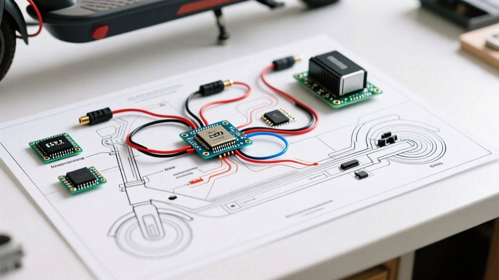

Architectural Overview of the Hover-1 36V Platform
Planning a custom build, repair, or battery upgrade requires a precise understanding of the underlying electrical architecture. The Hover 1 electric scooter wiring diagram for the popular Alpha and Titan 350W/500W platforms relies on a 36V nominal (42V peak) lithium-ion powertrain. Unlike generic clone scooters, Hover-1 utilizes a proprietary sine-wave controller with integrated UART communication for the LCD dashboard. This installation planning guide breaks down the exact wire gauges, pinout matrices, and routing protocols necessary to execute a flawless assembly or retrofit in 2026.
CRITICAL SAFETY WARNING: The 10S battery packs in these scooters can deliver over 30A of continuous current. Always disconnect the main XT60 or XT90 battery connector and cap the positive terminal with dielectric grease before probing the controller harness. Refer to the CPSC Battery Safety Guidelines for proper handling of high-density Li-ion cells.Core Wiring Diagram: Controller Pinout & Wire Gauge Matrix
The central hub of the Hover 1 electric scooter wiring diagram is the 36V 15A/22A brushless DC (BLDC) motor controller. Selecting the correct American Wire Gauge (AWG) is non-negotiable to prevent voltage sag and thermal throttling under load. Below is the definitive pinout matrix for the primary harness.
| Pin / Harness ID | Wire Color | Function | Required AWG | Connector Type |
|---|---|---|---|---|
| Power In (+) | Red | Main Battery Positive | 12 AWG | XT60 / XT90 |
| Power In (-) | Black | Main Battery Negative | 12 AWG | XT60 / XT90 |
| Phase A / B / C | Yellow / Green / Blue | BLDC Motor Phases | 14 AWG | 4.2mm Bullet |
| Hall Sensors | Multi (5-pin) | Rotor Position Feedback | 22 AWG | JST-SM 2.54mm |
| Throttle | Red/Blk/Grn | 5V, GND, Signal (0.8-3.6V) | 24 AWG | JST-XH 2.5mm |
| UART Display | Yellow/White | TX / RX Data Lines | 24 AWG | Higo Mini 4-Pin |
Pre-Installation Planning: Component Verification
Before routing a single wire through the steering column, you must validate the baseline components. As of 2026, many aftermarket Hover-1 battery replacements utilize Molicel P42A 21700 cells in a 10S4P configuration, pushing continuous discharge capabilities to 40A. Ensure your Battery Management System (BMS) is rated for at least 30A continuous and features over-current protection (OCP) set to 45A.
Validating the BMS and Cell Topology
According to Battery University's serial and parallel configuration standards, a 10S pack requires precise voltage balancing. Use a digital multimeter to measure the voltage across the BMS balance plug. The delta between the highest and lowest cell group must not exceed 0.05V before connecting to the controller. If the variance is higher, the BMS will bleed current during the ride, leading to premature low-voltage cutoffs (LVC) at 30.0V.
Motor Phase & Hall Sensor Routing Protocols
The most common point of failure in the Hover 1 electric scooter wiring diagram is the misalignment of the 3-phase BLDC motor wires and the 120-degree Hall effect sensors. The Hover-1 Alpha hub motor relies on three internal Hall sensors to track rotor position. If the controller's phase output does not perfectly match the motor's Hall sequence, the scooter will exhibit severe stuttering, draw upwards of 35A at a standstill, and instantly trip the BMS.
- Phase Wire Sequencing: Match Yellow-to-Yellow, Green-to-Green, and Blue-to-Blue. If the motor spins in reverse, swap only two phase wires (e.g., Yellow and Green) and reverse the corresponding Hall sensor signal wires to maintain alignment.
- Clearance Specifications: When routing the 14 AWG phase wires down the swingarm, maintain a minimum 15mm clearance from the steering column pivot and suspension dampener. Use split-loom tubing and secure it with UV-resistant zip ties every 40mm to prevent insulation abrasion during full lock-to-lock turns.
- Crimping Standards: Use an IWISS SN-28B ratchet crimper for all JST-SM 2.54mm pitch connectors on the 22 AWG hall sensor lines. Hand-crimping these micro-wires leads to intermittent signal loss under high-frequency vibration.
Step-by-Step Installation Sequence
- Chassis Grounding: Attach the main 12 AWG negative battery wire to the controller, then route the secondary ground to the scooter's aluminum deck using an M5 stainless steel bolt and star washer to ensure chassis grounding for EMI shielding.
- Controller Mounting: Apply a 2mm layer of thermal paste (e.g., Arctic MX-4) between the controller's aluminum heat sink and the scooter's internal mounting plate. Secure with M4 screws torqued to 2.5 Nm.
- Throttle Calibration: Connect the 3-pin JST-XH throttle harness. Before applying power, ensure the thumb throttle is at the zero position. The controller requires a 0.8V baseline signal on boot to prevent an 'Error 04' throttle fault code.
- Regenerative Braking Setup: Connect the electronic brake lever harness. The Hover-1 sine-wave controller supports regen, but it must be wired to the E-ABS pin, not the standard mechanical brake cut-off pin.
- Power-On Test: Connect the main XT60 battery lead. Expect a small spark due to the controller's internal 1000µF capacitors charging. To mitigate this, use an anti-spark XT90-S connector in future builds.
Common Failure Modes & Edge Cases
Expert Troubleshooting Insight: If your scooter cuts power abruptly while descending a steep hill, you are experiencing Regenerative Overvoltage. When the battery is at 100% charge (42.0V), the kinetic energy fed back into the system via regen can push the bus voltage to 43.5V. This triggers the BMS Over-Voltage Protection (OVP), shutting down the scooter mid-ride. Always begin rides with a battery state-of-charge below 95% if heavy regenerative braking is anticipated.
Another frequent edge case involves water ingress in the Higo Mini 4-pin display connector. Unlike standard JST connectors, Higo connectors feature internal O-rings. If the O-ring is pinched during installation, capillary action will draw moisture directly into the UART TX/RX lines, corrupting the data packets and causing the LCD to freeze while the scooter remains operational. Always apply a dab of dielectric grease to the male pins before mating Higo connectors.
Authoritative References & Compliance Standards
When modifying or repairing personal e-mobility devices, adherence to international safety standards is critical for both user safety and insurance compliance. The wiring practices outlined in this guide align with the IEC E-Mobility Systems Standards (specifically IEC 62133 for portable sealed secondary cells) and the UL 2272 certification requirements for electrical systems in personal e-mobility devices. Always verify that aftermarket replacement controllers carry appropriate CE and RoHS markings before integrating them into the Hover-1 harness.