
The Gap Between Schematic Logic and Physical Wiring
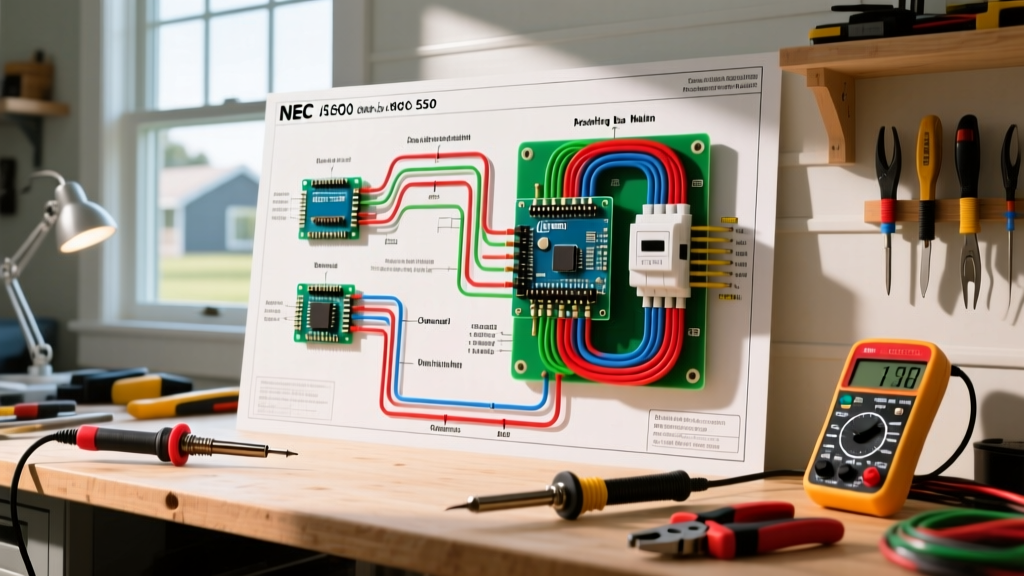
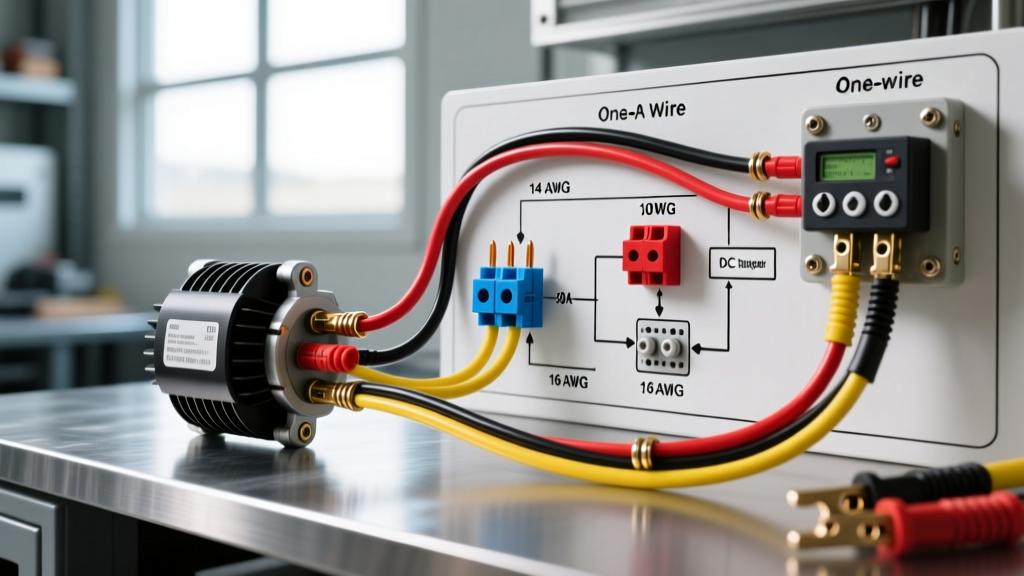
When an engineer or technician reviews a schematic diagram of electrical wiring, they are looking at the logical flow of a circuit. Schematics illustrate how components interact, utilizing standardized symbols to represent relays, contactors, and loads. However, a schematic rarely dictates the physical reality of the installation. A 14 AWG control wire and a 2/0 AWG feeder cable might be drawn with the exact same line weight on a CAD print. Bridging the gap between the abstract logic of a schematic and the physical requirements of wire gauge and insulation color is where many electrical failures originate.
As we navigate the 2026 industrial and residential electrical landscape, adherence to the National Electrical Code (NEC) is non-negotiable. Misinterpreting a schematic diagram of electrical wiring can lead to undersized conductors, catastrophic voltage drop, or dangerous neutral-to-ground faults. This guide provides a comprehensive framework for translating schematic annotations into physical wire selection, focusing on precise gauge sizing and NEC-mandated color codes.
Decoding Wire Gauges from Schematic Annotations
In a professional schematic diagram of electrical wiring, wire gauges are not drawn to scale. Instead, they are identified by annotation tags (e.g., W1-12AWG-THHN) or specified in a separate bill of materials (BOM). The most critical error a junior technician can make is assuming that the 90°C ampacity column in NEC Table 310.16 dictates the overcurrent protection size. Due to NEC Article 240.4(D), small conductors have strict overcurrent limits regardless of their insulation temperature rating.
NEC Ampacity vs. Overcurrent Protection Limits
The table below contrasts the physical properties of copper conductors with their strict NEC overcurrent protection limits. Always size your breakers based on the Overcurrent Limit column, not the 90°C ampacity, unless specific engineering derating calculations apply.
| AWG Size | Diameter (Inches) | 75°C Ampacity | 90°C Ampacity | NEC 240.4(D) Max Breaker |
|---|---|---|---|---|
| 14 AWG | 0.0641 | 20A | 25A | 15A |
| 12 AWG | 0.0808 | 25A | 30A | 20A |
| 10 AWG | 0.1019 | 35A | 40A | 30A |
| 8 AWG | 0.1285 | 50A | 55A | 40A (Standard sizing) |
| 6 AWG | 0.1620 | 65A | 75A | 60A (Standard sizing) |
Expert Insight: If your schematic diagram of electrical wiring indicates a 20A motor circuit located 150 feet from the panel, 12 AWG wire is physically illegal due to voltage drop. You must upsize to 10 AWG or 8 AWG to maintain a voltage drop below 3%, even though the breaker remains at 20A.
The NEC Color Code Matrix vs. Schematic Line Colors
Schematic software often defaults to arbitrary line colors—red for DC positive, black for DC negative, or blue for AC control lines. Physical wiring, however, must strictly follow NFPA 70: National Electrical Code (NEC) standards for identification. Installing a physical panel that mimics the colors of a CAD schematic is a direct code violation and a severe safety hazard.
Standard US NEC AC Power Color Codes
For standard 120/208V and 277/480V three-phase systems, the NEC mandates specific phase, neutral, and ground colors. Below is the definitive translation matrix from schematic logic to physical wire.
| System Voltage | Phase A | Phase B | Phase C | Neutral | Ground (EGC) |
|---|---|---|---|---|---|
| 120/208V 3-Phase | Black | Red | Blue | White | Green / Bare |
| 277/480V 3-Phase | Brown | Orange | Yellow | Gray | Green / Bare |
| 120/240V Single-Phase | Black | Red | N/A | White | Green / Bare |
| 240V High-Leg Delta | Black | Orange (High Leg) | Blue | White | Green / Bare |
Note: The High-Leg Delta system is a common edge case. The 'B' phase yields 208V to neutral and must be identified by the color Orange per NEC 110.15 and 215.8. A schematic diagram of electrical wiring rarely highlights this physical danger, making field verification mandatory.
Step-by-Step: Translating a Schematic to a Physical Wiring Plan
To ensure your physical installation matches the intent of the schematic diagram of electrical wiring without violating code, follow this rigorous translation framework:
- Isolate Power vs. Control Circuits: Schematics usually separate high-voltage power (e.g., 480V 3-phase) from low-voltage control (e.g., 24V DC or 120V AC). Control wiring inside a panel typically utilizes 14 AWG MTW (Machine Tool Wire) or 18 AWG for low-current PLC I/O, while power wiring follows the THHN/THWN-2 sizing rules.
- Calculate Voltage Drop for Long Runs: Schematics assume ideal zero-resistance wires. In reality, you must calculate voltage drop using the formula:
VD = (2 × K × I × L) / CM. For copper, K is 12.9. If a schematic shows a 15A load 200 feet away, using 12 AWG (CM=6530) yields a 7.9V drop on a 120V circuit (6.5%), which exceeds the 3% NEC recommendation. You must upsize to 10 AWG. - Verify Insulation Ratings: Check the schematic's environmental notes. If the wiring passes through a wet location or a high-temperature ambient zone, standard THHN is insufficient. You must specify XHHW-2 or THWN-2, which offer superior moisture and chemical resistance.
- Apply Torque Specifications: A perfect schematic and correctly sized wire will still fail if terminations are loose. Modern NEC 110.14(D) requires terminations to be torqued to the manufacturer's specifications. Use a calibrated torque screwdriver (e.g., CDI 401SM) to apply the exact inch-pounds specified on the breaker or lug.
Critical Edge Cases and Failure Modes
The Multi-Wire Branch Circuit (MWBC) Trap
A schematic diagram of electrical wiring might show two separate 120V circuits sharing a single neutral wire to save material. In the physical world, this is an MWBC. If the red and black phase wires are accidentally landed on the same phase in the panel, the shared neutral will carry the sum of both currents (e.g., 20A + 20A = 40A), melting a 14 AWG or 12 AWG neutral wire without tripping a breaker. NEC 210.4 mandates that MWBCs must be on opposite phases and utilize a simultaneous disconnect (handle tie).
International Harmonized (IEC) vs. NEC Clashes
When importing OEM machinery from Europe, the provided schematic diagram of electrical wiring will use IEC color codes: Brown, Black, and Gray for phases, and Blue for neutral. If you are integrating this machine into a US facility, the physical wires inside the machine's internal panel are grandfathered, but any field wiring you add to connect the machine to the facility must strictly follow US NEC colors (Black, Red, Blue, White). Mixing IEC Blue (Phase) with NEC Blue (Phase C) in a shared junction box is a recipe for catastrophic phase-to-phase faults.
Essential Tools for Schematic Verification
Translating schematics into safe physical wiring requires precision tools. Relying on visual estimation is a hallmark of amateur work. Equip your team with the following:
- Fluke 117 True RMS Multimeter (~$215): Essential for verifying phase-to-neutral voltages and ensuring the physical wiring matches the schematic's expected voltage levels before energizing control circuits.
- Klein Tools 11055 Wire Stripper (~$30): Specifically designed for 10-14 AWG solid and stranded wire. Using the wrong stripper notch nicks the copper, reducing the circular mil area and creating a localized hot spot.
- Wiha Insulated Torque Screwdriver (~$150): Crucial for meeting NEC 110.14(D) torque requirements on breakers and terminal blocks, preventing arc faults caused by loose mechanical connections.
Final Thoughts on Schematic Fidelity
A schematic diagram of electrical wiring is the blueprint, but the NEC is the law. The most dangerous assumption an electrician can make is that the schematic designer accounted for every physical variable, from ambient temperature derating to voltage drop over long conduit runs. By rigorously applying NEC ampacity tables, strictly adhering to phase and neutral color codes, and verifying every termination with calibrated tools, you ensure that the logical brilliance of the schematic translates into a safe, code-compliant, and reliable physical installation. For further reading on workplace electrical safety and compliance, always consult the latest guidelines from OSHA Electrical Safety Standards and resources from the Electrical Safety Foundation International (ESFI).