
The Critical Role of Audible Alarms in Commercial Appliances
When a commercial walk-in freezer drops below safe temperature thresholds, or an industrial HVAC system experiences a high-pressure fault, visual indicators on a control board are rarely enough. You need an immediate, unmistakable auditory warning. Integrating an audible signaling device into heavy-duty equipment requires a precise understanding of control voltages, relay logic, and current draws. In this comprehensive appliance wiring tutorial, we break down the exact wiring diagram for horn installations, focusing on 24VAC commercial systems and 12VDC off-grid/RV appliances.
As of 2026, modern appliance control boards are highly sensitive solid-state systems. Wiring a high-draw motorized horn directly to a printed circuit board (PCB) alarm terminal is a guaranteed way to fry the board's internal traces. This guide will show you how to use intermediary relays to protect your equipment while ensuring your alarm sounds reliably when a fault occurs.
Appliance Horn Classifications: Motorized vs. Piezo vs. Electronic
Before pulling wire, you must select the correct signaling appliance for your environment. The choice dictates your wire gauge, relay sizing, and power supply requirements.
| Horn Type | Model Example (2026) | Typical Draw | Decibel (dB) | Best Appliance Application |
|---|---|---|---|---|
| Motorized | Edwards Signaling 552-1 | ~0.75A (24VAC) | 100 dB | Walk-in freezers, boiler rooms |
| Piezo Buzzer | Mallory SC628 | ~0.02A (12-28VDC) | 105 dB | RV fridges, portable generators |
| Electronic Siren | Federal Signal 118 | ~1.2A (12VDC) | 118 dB | Outdoor commercial HVAC units |
Note: Motorized horns draw significant inrush current. Always verify the locked-rotor amperage (LRA) if specified by the manufacturer, as it can briefly spike 30% higher than the running amperage.
Core Components for a Safe Horn Circuit
To execute the wiring diagram for horn integration safely, gather the following components. Prices reflect average 2026 industrial supply costs:
- Intermediary Relay: Omron G2R-2-S (24VAC coil, 10A contacts) — ~$14.00. This isolates the delicate appliance control board from the heavy current of the horn.
- Wire Gauge: 16 AWG stranded copper for runs exceeding 25 feet; 18 AWG for shorter runs. Do not use 22 AWG thermostat wire for motorized horns.
- Flyback Diode (For DC Setups): 1N4007 rectifier diode (~$0.10). Mandatory when switching DC relay coils to prevent inductive voltage spikes from destroying the appliance PCB.
- Inline Fuse Holder: Littelfuse ATO blade fuse holder with a 3A or 5A fuse, placed within 6 inches of the power source.
Step-by-Step Wiring Diagram for Horn (24VAC Commercial Setup)
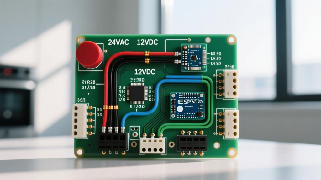
This schematic translates the visual wiring diagram for horn setups into actionable terminal connections. We will assume a standard commercial refrigeration control board that outputs 24VAC across terminals ALM-C (Alarm Common) and ALM-NO (Alarm Normally Open) during a fault condition.
Phase 1: The Control Side (Low Current)
- Power Down: Lock out and tag out (LOTO) the main 240V/120V disconnect feeding the commercial appliance.
- Run Control Wire: Run an 18 AWG 2-conductor cable from the appliance control board's
ALM-CandALM-NOterminals to your relay enclosure. - Connect to Relay Coil: Wire
ALM-Cto the Omron relay'sA1coil terminal. WireALM-NOto theA2coil terminal. When a fault occurs, the board closes the circuit, energizing the 24VAC coil.
Phase 2: The Load Side (High Current)
- Source Dedicated Power: Do not pull load power from the control board transformer. Tap into a dedicated 24VAC transformer (minimum 40VA) or the appliance's main 24VAC bus bar.
- Wire the Fuse: Connect the 24VAC hot source to the inline 5A fuse holder.
- Relay Switching: Run the fused 24VAC line into the relay's
COM(Common) terminal. - Horn Connection: Connect the relay's
NO(Normally Open) terminal to the positive/line terminal of the Edwards 552-1 horn. - Complete the Circuit: Wire the horn's negative/neutral terminal back to the 24VAC common bus bar.
Pro-Tip for DC Appliance Boards (12V/24VDC): If you are wiring a piezo or electronic horn to a 12VDC RV appliance board, the coil wiring remains similar, but you must solder a 1N4007 flyback diode across the relay'sA1andA2terminals (stripe facing A1). When the DC coil de-energizes, the collapsing magnetic field creates a reverse voltage spike that can instantly destroy solid-state appliance PCBs.
Troubleshooting Edge Cases and Failure Modes
Even with a perfect wiring diagram for horn installation, real-world conditions introduce variables. Here is how to diagnose the most common field failures.
The 'Humming but Not Sounding' Motorized Horn
Symptom: The Edwards 552-1 horn emits a low electrical hum, the internal rotor vibrates, but the centrifugal weights fail to engage the striker plate.
Root Cause: Severe voltage drop. Motorized solenoids require at least 85% of nominal voltage to actuate fully. If you used 22 AWG wire over a 60-foot run, the resistance will drop your 24VAC supply down to 18VAC by the time it reaches the horn.
Fix: Upgrade the load-side wiring to 14 AWG or 16 AWG stranded copper. Always measure voltage at the horn terminals under load using a true-RMS multimeter.
The 'Ghost Trigger' Alarm
Symptom: The horn sounds randomly when large compressor contactors engage, even though no fault code is present on the appliance board.
Root Cause: Electromagnetic interference (EMI) inducing a transient voltage in the alarm control wires, tricking the solid-state relay or PCB.
Fix: Route the low-voltage alarm control wires in a separate conduit from the high-voltage compressor lines. If they must cross, ensure they intersect at exactly 90 degrees. Shielded 18 AWG cable (with the drain wire grounded at the panel only) is highly recommended for noisy industrial environments.
Compliance: NEC and OSHA Standards for 2026
When integrating alarms into commercial and industrial appliances, adherence to safety codes is non-negotiable. According to the NFPA 70 (National Electrical Code), Article 725 governs Class 1, Class 2, and Class 3 remote-control and signaling circuits. Your horn wiring must be physically separated from Class 1 power conductors unless separated by a physical barrier or insulated raceway.
Furthermore, if the appliance serves as a life-safety or emergency warning system in a commercial kitchen or warehouse, it must comply with OSHA Standard 1910.165 regarding employee alarm systems. This dictates that the audible signal must exceed the ambient noise level of the facility by at least 15 decibels, or 5 decibels above the maximum intermittent noise level, whichever is greater. Always perform a decibel survey using a calibrated SPL meter post-installation.
For fire-linked appliance shutdowns and alarms, referencing the NFPA 72 (National Fire Alarm and Signaling Code) is essential to ensure your signaling appliances are UL-listed for the specific environmental conditions (e.g., damp, high-heat, or corrosive atmospheres) present in your facility.
Frequently Asked Questions (FAQ)
Can I wire a horn directly to an Arduino or microcontroller in a DIY smart appliance?
No. Microcontrollers output logic-level voltages (3.3V or 5V) and can only source 20mA to 40mA of current. A standard horn draws hundreds of milliamps to over an amp. You must use a logic-level MOSFET (like an IRLZ44N) or an opto-isolated relay module to bridge the microcontroller signal to the horn's power supply.
Do piezo buzzers require a flyback diode?
Standard passive piezo elements are capacitive, not inductive, and generally do not require a flyback diode. However, if you are using an active piezo buzzer with an internal oscillator circuit, or a mechanical magnetic buzzer with an internal coil, you should place a reverse-biased diode across the terminals to protect your switching transistor.
What is the maximum distance I can run 18 AWG wire to a 24VAC horn?
For a standard 0.75A motorized horn, 18 AWG copper wire has a resistance of roughly 6.38 ohms per 1,000 feet. To maintain a voltage drop below 10% (2.4V), your total round-trip wire length should not exceed 300 feet. However, for mechanical reliability and physical durability in commercial appliance environments, it is best practice to limit 18 AWG runs to under 100 feet and upgrade to 16 AWG for longer distances.