
Understanding the 3-Way Switch Circuit Architecture
A 3-way switch allows you to control a single lighting load or receptacle from two distinct physical locations, such as the top and bottom of a staircase or opposite ends of a hallway. Unlike standard single-pole switches, 3-way switches do not have "ON" or "OFF" markings on the toggle. Instead, they rely on a mechanical internal mechanism that routes current between a common terminal and one of two traveler terminals.
When reviewing a wiring diagram for 3 way switch configurations, it is critical to identify the three primary circuit segments: the line (power source), the load (the light fixture), and the traveler run (the interconnect between the two switches). Misidentifying the common terminal is the most frequent cause of failure in DIY installations. On modern devices like the Leviton Decora 5603-2W or the Lutron Maestro MACL-153M, the common terminal is typically a dark brass or black-colored screw, while the traveler terminals are lighter brass.
The Two Primary Wiring Diagram Configurations
While there are several ways to route cables depending on the physical framing of your home, residential wiring generally falls into two main diagram topologies. Below, we break down the exact wire routing for both scenarios.
Configuration A: Power Source at the First Switch (Most Common)
In this layout, the main power feed from the breaker panel enters the first switch box. This is the most straightforward diagram to execute and requires standard 2-wire and 3-wire NM-B (Romex) cables.
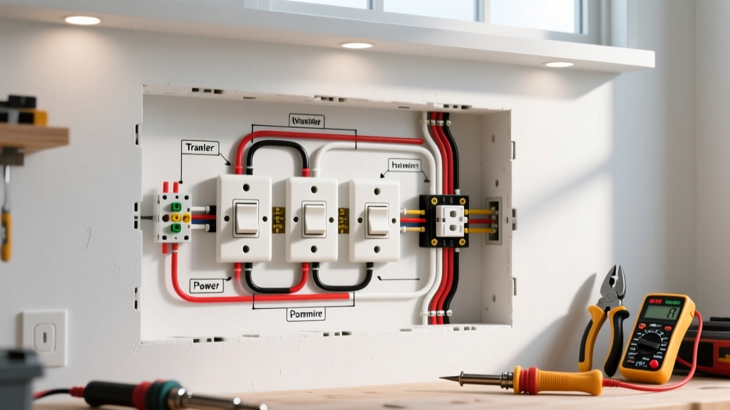
- At Switch 1 (Line Side): The black (hot) wire from the power source connects directly to the Common terminal. The white (neutral) wire is spliced to the white neutral wire of the 3-wire cable heading toward Switch 2. The red and black wires of the 3-wire cable connect to the two Traveler terminals.
- At Switch 2 (Load Side): The red and black wires from the incoming 3-wire cable connect to the Traveler terminals. The white wire from this 3-wire cable connects to the Common terminal (Note: Because this white wire is acting as a switched hot, NEC code requires it to be re-identified with black electrical tape or paint at both ends). A 2-wire cable then runs from Switch 2 to the light fixture, with the black wire connecting to the fixture's hot lead and the white to the neutral.
Configuration B: Power Source at the Light Fixture
This diagram is common in retrofits or when the ceiling fixture is physically located between the two wall switches. It requires running 3-wire cables from the light to both switch locations.
- At the Light Fixture: The incoming hot (black) from the panel connects to the white wire of the 3-wire cable heading to Switch 1 (re-identified as hot with black tape). The incoming neutral (white) connects to the fixture's neutral. The black wire of the 3-wire cable connects to the fixture's hot lead.
- At Switch 1: The re-identified white wire (hot) connects to the Common terminal. The black and red wires connect to the Travelers. A second 3-wire cable runs to Switch 2, with its black and red wires spliced to the travelers, and its white wire spliced to the black wire heading to Switch 2's common.
- At Switch 2: The white wire (re-identified as hot) connects to the Common terminal. The black and red wires connect to the Travelers.
Expert Tip: Always use a non-contact voltage tester and a multimeter to verify the line and load wires before disconnecting old switches. Relying on wire color alone in older homes can lead to dangerous miswiring, as previous owners may have deviated from standard color codes.
Wire Gauge, Ampacity, and Breaker Sizing Matrix
Selecting the correct wire gauge is non-negotiable for fire safety and compliance. The following table outlines the standard specifications for 120V residential lighting circuits.
| Wire Gauge (AWG) | Max Breaker Size | Max Load (Watts @ 120V) | Typical Application |
|---|---|---|---|
| 14 AWG | 15 Amp | 1,440W (Continuous) | Standard residential lighting circuits, low-draw LED fixtures. |
| 12 AWG | 20 Amp | 1,920W (Continuous) | Circuits sharing lighting and receptacles, or high-draw incandescent/halogen arrays. |
| 10 AWG | 30 Amp | N/A for standard lighting | Rarely used for lighting; reserved for heavy appliances (dryers, water heaters). |
Critical NEC Code Requirements for 2026 Compliance
When executing any wiring diagram for 3 way switch installations, you must adhere to the latest National Electrical Code (NEC) standards. The National Fire Protection Association (NFPA) has updated several articles in recent cycles that directly impact switch wiring.
NEC Article 404.2(C): Neutral Conductor at Switch Boxes
Perhaps the most impactful modern code change is the requirement for a neutral wire at virtually all switch locations. This was implemented to accommodate smart switches, timers, and occupancy sensors which require a continuous low-current path to operate their internal Wi-Fi or Zigbee radios.
How to comply: Even if you are installing a "dumb" mechanical 3-way switch, you must route the neutral wire into the switch box and cap it off with a wire nut and electrical tape. Do not leave the neutral un-pulled inside the wall cavity. If you upgrade to a smart switch later (like the Lutron Caseta PD-6ANS), you will need that neutral to complete the circuit.
NEC Article 250.148: Equipment Grounding Conductors
All metal switch boxes and the grounding screws on the switches themselves must be bonded to the circuit's equipment grounding conductor (bare copper or green). According to Occupational Safety and Health Administration (OSHA) guidelines and NEC standards, a grounding pigtail must be used if multiple ground wires enter a metal box, ensuring the box remains grounded even if a device is removed.
Pro-Tips for Flawless Terminations and Torque
Electrical fires are frequently caused by loose terminal connections that arc and generate immense heat over time. To ensure a professional-grade installation:
- Strip to the Gauge: Use the strip gauge molded into the back of the switch. For most Leviton and Lutron 15A/20A devices, this is exactly 3/4 inch. Exposing too much bare copper creates a shock hazard; too little results in the screw biting into the wire insulation, leading to a high-resistance connection.
- Form the J-Hook Correctly: When using side-wire terminal screws, bend the stripped wire into a hook using needle-nose pliers. The hook must wrap around the screw in a clockwise direction. This ensures that tightening the screw pulls the wire loop tighter rather than pushing it out.
- Use a Torque Screwdriver: The NEC now mandates that terminations be torqued to the manufacturer's specifications. For standard 15A residential switches, this is typically between 12 and 14 inch-pounds. A calibrated torque screwdriver (such as the Klein Tools 70550) eliminates guesswork and prevents stripped screws or crushed wire strands.
Troubleshooting Matrix: Common 3-Way Failures
If your newly wired 3-way circuit is malfunctioning, use this diagnostic matrix to isolate the fault. Always ensure the breaker is OFF before opening the boxes to inspect physical connections.
| Symptom | Probable Cause | Diagnostic Fix |
|---|---|---|
| Light only turns on/off from Switch 1; Switch 2 does nothing. | Switch 2 is wired incorrectly, or the common terminal on Switch 2 is connected to a traveler. | Verify the dark brass/black screw on Switch 2 is connected to the load (or line) hot, not a traveler wire. |
| Light toggles on/off, but the switches must be in opposite positions to work. | Traveler wires are crossed or misidentified between the two switches. | Ensure the two traveler wires (usually red and black of a 3-wire cable) are connected exclusively to the light brass screws on both switches. |
| Breaker trips immediately when toggling either switch. | Direct short circuit; hot wire is touching ground or neutral, or the white "switched hot" wire is not isolated. | Check all wire nuts. Ensure the re-identified white wire in the traveler run is not accidentally spliced to the true neutral bundle. |
| Light flickers or hums when using LED bulbs. | Incompatible dimmer switch or lack of a neutral wire causing current leakage through the LED driver. | Upgrade to an LED-compatible 3-way dimmer (e.g., Lutron Diva DVCL-153P) and ensure the neutral is connected if required. |
Frequently Asked Questions
Can I use a 3-way switch as a single-pole switch?
Yes. To use a 3-way switch in a single-pole application, connect the line hot wire to the Common terminal and the load wire to one of the Traveler terminals. Leave the second traveler terminal empty and capped. The switch will function normally, though the toggle orientation (up/down for on/off) may be inverted depending on which traveler you used.
Does it matter which traveler wire goes to which traveler screw?
No. The two traveler screws on a 3-way switch are electrically interchangeable. Swapping the red and black traveler wires at one or both switches will not affect the circuit's operation or violate any NEC codes, provided they are both securely terminated on the light brass screws.