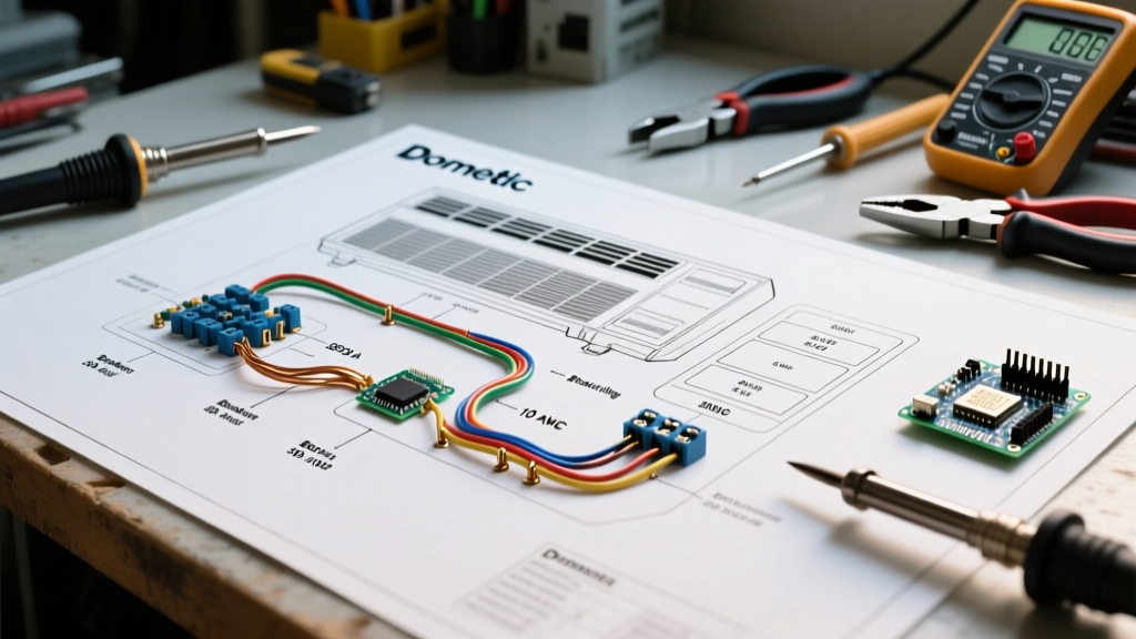

Decoding the Wiring Diagram for Neutral Safety Switch Circuits
The neutral safety switch (NSS), frequently designated in modern vehicles as the Transmission Range Sensor (TRS) or Park/Neutral Position (PNP) switch, is a critical powertrain interlock device. Its primary function is to interrupt the starter solenoid circuit unless the transmission is in Park or Neutral. Simultaneously, it routes power to the reverse illumination circuit and provides logic-level signals to the Powertrain Control Module (PCM) for fuel injection and ignition timing mapping.
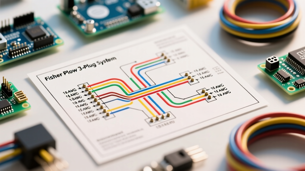
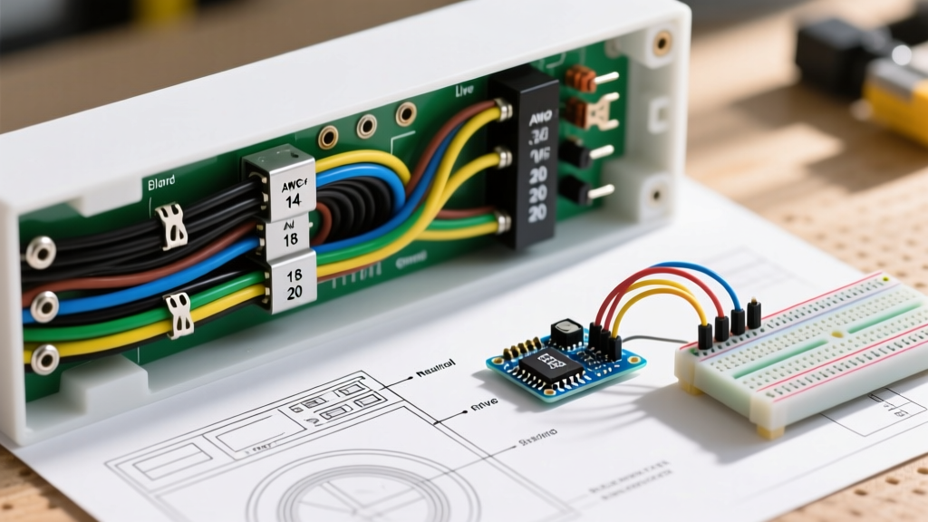
When diagnosing a no-crank condition, erratic shifting, or malfunctioning backup lights, relying on a generic wiring diagram for neutral safety switch systems is insufficient. You must understand the specific wire gauges required to handle inrush currents, as well as the OEM color codes used to trace these circuits through complex engine bay harnesses. This reference guide breaks down the exact electrical specifications, diagnostic procedures, and edge cases required for professional-grade repairs.
Standard Wire Gauge Specifications (AWG)
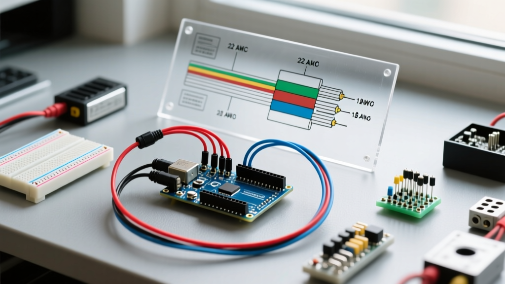
One of the most common mistakes DIYers make when repairing an NSS harness is replacing factory wiring with undersized aftermarket wire. The circuit from the ignition switch, through the NSS, to the starter solenoid 'S' terminal is not a simple low-current signal path. It must handle the initial 'pull-in' winding spike of the starter solenoid.
Engineering Note: The starter solenoid contains two windings. The pull-in winding draws a massive inrush current (often 30A to 45A) for a fraction of a second to physically engage the drive pinion. Once engaged, the hold-in winding maintains the connection at a much lower current (~5A). If the wire gauge between the NSS and the solenoid is too thin, the voltage drop during the pull-in phase will cause a 'single click' no-crank failure.
| Circuit Path | Recommended AWG | Max Ampacity | Engineering Rationale |
|---|---|---|---|
| Ignition Feed to NSS | 12 AWG | 20A - 25A | Handles continuous cranking load without excessive voltage drop over long harness runs. |
| NSS to Starter Solenoid (S-Terminal) | 10 AWG or 12 AWG | 30A - 40A | Critical for surviving the momentary high-amperage spike of the solenoid pull-in coil. |
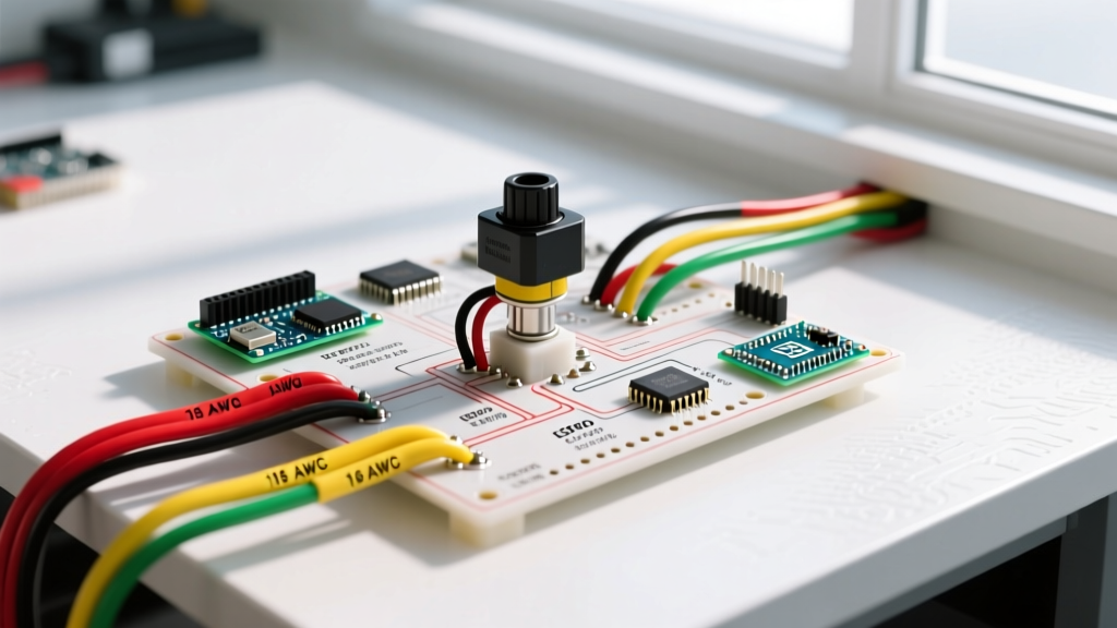
| NSS to Reverse Lights | 16 AWG or 18 AWG | 6A - 10A | Sufficient for standard 1156 or LED backup bulbs (typically 2A to 4A total draw). |
| NSS to PCM (Logic Signal) | 20 AWG or 22 AWG | 2A - 3A | Low-current logic path; requires minimal gauge but high-quality shielding to prevent EMI. |
OEM Automotive Color Code Reference
While exact color codes vary by manufacturer, model year, and specific harness routing, the automotive industry relies on standardized base colors and tracer stripes to identify circuit functions. When reading a wiring diagram for neutral safety switch applications, you will typically encounter the following color conventions:
General Motors (Chevy, GMC, Cadillac)
- Pink: Switched ignition feed (Hot in 'Start' and 'Run').
- Purple or Yellow: Starter solenoid trigger output (Hot only in 'Start' while in Park/Neutral).
- Light Green: Reverse light feed.
- Black/White: PCM ground reference or logic signal return.
Ford (F-Series, Mustang, Explorer)
- Red/Light Blue Stripe: Starter relay trigger feed from ignition switch.
- White/Purple Stripe: Output to starter solenoid relay.
- Brown/Pink Stripe or Black/Pink: Reverse lamp circuit.
Honda / Acura / Toyota
- Black/White or Black/Yellow: Main ignition power feed.
- Yellow/Red or Black/Red: Starter cut relay trigger.
- Green/White or Green/Black: Backup light output.
Pro Tip: Always use a digital multimeter (DMM) to verify wire function rather than relying solely on color. Previous owners or aftermarket alarm installers frequently splice in non-standard wires, rendering factory color codes unreliable.
Step-by-Step Multimeter Diagnostics
To properly validate the wiring diagram for neutral safety switch integrity, you must perform both continuity and voltage drop tests. A simple continuity test will not reveal high-resistance corrosion inside the bulkhead connectors.
1. The Voltage Drop Test (Cranking Condition)
- Set your DMM (such as a Fluke 87V) to DC Volts.
- Connect the red probe to the battery positive terminal and the black probe to the NSS output terminal (the wire leading to the starter solenoid).
- Have an assistant turn the key to the 'Start' position (or press the push-button start while holding the brake).
- Pass Criteria: The voltage drop should be less than 0.5V. If you read 1.5V or higher, you have high resistance in the ignition switch, the NSS contacts, or the wiring harness.
2. The Continuity & Resistance Test (Key Off)
- Disconnect the NSS electrical connector.
- Set the DMM to Ohms (200Ω range).
- Place probes across the Park/Neutral terminals on the switch itself.
- Move the shifter through all gears. You should see near-zero resistance (< 1.0Ω) in Park and Neutral, and infinite resistance (OL) in all drive gears.
Edge Cases: Aftermarket Remote Starts & Alarm Bypasses
One of the most frequent causes of NSS circuit failure in modern vehicles is the improper installation of aftermarket remote start modules or security alarms. Installers often use 'Scotch-Lok' tap connectors to intercept the starter trigger wire at the NSS or ignition switch.
These piercing connectors frequently fail to penetrate the copper strands properly, leading to galvanic corrosion and severe voltage drop over time. Furthermore, remote start modules require a 'Park/Neutral' logic input to verify the vehicle is safe to start remotely. If the installer taps the 20 AWG PCM logic wire with a heavy 14 AWG wire, the added weight and stress can pull the pin out of the delicate Delphi or TE Connectivity connector housing, resulting in a persistent Check Engine Light (e.g., P0705 Transmission Range Sensor Circuit Malfunction).
Corrective Action: Always remove Scotch-Loks. Solder and seal splices using marine-grade heat shrink tubing with adhesive lining, or use proper T-tap connectors with dielectric grease. For logic signals, use a high-impedance buffer relay or an opto-isolator to prevent drawing current directly from the PCM signal wire.
Sourcing OEM-Grade Connectors & Repair Kits
If the NSS connector housing is melted, brittle, or the pins are backed out, do not attempt to reuse it. Sourcing OEM-grade pigtails is essential for maintaining weatherproof seals. In 2026, standard 4-pin to 8-pin NSS pigtails (such as the ACDelco PT2254 or Motorcraft WPT-1246 series) typically retail between $18 and $45, depending on the pin count and sealing requirements.
When repairing these harnesses, ensure you are using terminals that match the specific cavity size of the connector. For deep-dive specifications on automotive connector cavities and wire seal standards, refer to the TE Connectivity Automotive Connectors engineering catalogs. Furthermore, all primary automotive wiring should meet the thermal and abrasion resistance requirements outlined in the SAE International J1128 Standard for low-tension primary cables.
For comprehensive diagnostic flowcharts regarding starter interlocks and no-crank scenarios, the AA1Car Automotive Diagnostics library remains an invaluable resource for cross-referencing OEM technical service bulletins (TSBs) related to NSS micro-switch failures.
Summary
Successfully navigating a wiring diagram for neutral safety switch circuits requires more than just tracing lines on a schematic. It demands an understanding of inrush current dynamics, strict adherence to AWG sizing, and meticulous attention to OEM color codes and connector integrity. By applying the voltage drop testing methods and sourcing correct replacement materials outlined above, you can permanently resolve no-crank and reverse-light anomalies with professional precision.