
Bridging High-Voltage Panels and Low-Voltage AV Routing
When designing a modern smart home or dedicated home theater, the intersection of high-voltage electrical panels and low-voltage audiovisual infrastructure is where most critical failures occur. Electricians and AV integrators often speak different languages, leading to compromised signal integrity. A comprehensive wiring diagram for HDMI cable infrastructure is not just about connecting Point A to Point B; it is about navigating the electromagnetic interference (EMI) generated by your main breaker panel, managing dedicated circuits, and properly terminating signals within a Structured Media Enclosure (SME).
In 2026, with the widespread adoption of HDMI 2.1a and the emerging HDMI 2.2 standards pushing uncompressed 8K at 120Hz and 10K resolutions, the bandwidth requirements have skyrocketed to 48 Gbps and beyond. At these frequencies, copper HDMI cables act as highly sensitive antennas. If routed improperly near a 200-amp main service panel or high-load AFCI (Arc Fault Circuit Interrupter) breakers, the magnetic flux will induce bit-error rates (BER) that cause HDCP handshake failures and screen flickering. This guide provides the definitive panel and breaker perspective on routing, protecting, and terminating HDMI infrastructure.
The Core Wiring Diagram for HDMI Cable Infrastructure
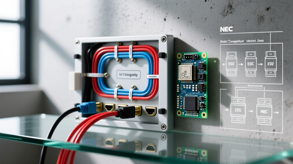
Before pulling wire, you must map the signal flow and power topology. Below is a text-based schematic representing a best-practice structured wiring diagram for HDMI cable runs originating from a centralized AV rack and terminating at a display, with specific attention to breaker panel separation.
Schematic Flow: AV Rack to Display
[120V Dedicated 20A Breaker] --> [Double-Conversion UPS / Power Conditioner] --> [AV Matrix Switcher] --> [Fiber Optic HDMI 2.1a Cable] --> [Low-Voltage Mud Ring / Wall Plate] --> [Display Device]
Critical Constraint: The Fiber Optic HDMI run must maintain a minimum 12-inch physical separation from any Romex/NM-B high-voltage wiring and breaker bus bars throughout the entire conduit path.
Understanding the Power Topology
The most overlooked aspect of HDMI wiring diagrams is the power source. Modern active HDMI cables and fiber optic HDMI cables (like those from Ruipro or FIBBR) require 5V power injection, typically drawn from the source device's HDMI pin 18. If your AV matrix or source equipment is plugged into a standard 15A lighting circuit shared with dimmer switches or variable frequency drives (VFDs) from HVAC systems, the dirty power will modulate the 5V rail, causing the active HDMI chipset to reset intermittently. Always map your AV panel to a dedicated 20A circuit originating from a standard thermal-magnetic breaker, avoiding AFCI/GFCI breakers if local NEC amendments permit dedicated AV equipment exemptions.
NEC Compliance: Low-Voltage AV vs. Breaker Panels
Adhering to the NFPA 70 National Electrical Code (NEC) is non-negotiable for safety and signal integrity. HDMI cables are classified as Class 2 circuits under NEC Article 725. According to Article 725.136(A), Class 2 circuit conductors must be separated by at least 2 inches (50 mm) from electric light, power, and Class 1 circuit conductors unless they are separated by a continuous and firmly fixed nonconductor or raceway.
However, the 2-inch minimum is a safety baseline, not a signal integrity guarantee. For 48 Gbps HDMI signals, a 2-inch separation from a 200A main service feeder is vastly insufficient to prevent EMI. The magnetic field generated by high-amperage breaker bus bars can easily penetrate standard PVC conduit.
Practical Separation Guidelines for AV Integrators
- Parallel Runs: Never run HDMI cables parallel to high-voltage Romex. If unavoidable, maintain a minimum 12-inch separation for runs exceeding 6 feet.
- Perpendicular Crossings: Always cross high-voltage wiring at a 90-degree angle to minimize the induction footprint.
- Structured Media Enclosures (SME): When using panels like the Leviton 47605-14C or OnQ enclosures, utilize the built-in physical barriers. Route all 120V power modules on the left side of the enclosure and all low-voltage HDMI keystones and patch cables on the right side.
- Conduit Shielding: If you must route near a breaker panel, pull the HDMI cable through flexible metallic conduit (FMC) or rigid metal conduit (RMC) and bond it to ground to create a Faraday cage effect against breaker EMI.
Copper vs. Fiber Optic HDMI: Panel Routing Matrix
Selecting the right cable type is heavily dependent on the distance from your structured panel to the display and the environmental EMI profile. The HDMI Licensing Administrator Premium Certification ensures baseline compliance, but physical construction dictates panel routing viability.
| Cable Type | Max Passive Run (48 Gbps) | Min. Bend Radius | EMI Vulnerability | Best Panel Use Case |
|---|---|---|---|---|
| Certified Copper (Passive) | 3 Meters (approx. 10 ft) | 4x Cable Diameter | High (Acts as antenna) | In-room AV racks directly behind displays; short SME patch cables. |
| Active Copper (Amplified) | 10 Meters (approx. 33 ft) | 5x Cable Diameter | Moderate (Shielding dependent) | Single-story runs where conduit avoids main breaker zones. |
| Fiber Optic HDMI (Hybrid) | 30+ Meters (100+ ft) | 20mm (Strict limit) | Zero (Photonic transmission) | Long runs through high-EMI zones, near breaker panels, and between floors. |
Expert Note: Fiber optic HDMI cables are completely immune to electromagnetic interference from breaker panels because the signal is transmitted via light pulses rather than electrical current. However, the copper ends still contain active transceiver chips that are sensitive to voltage drops. Ensure your source panel provides clean 5V power.
Step-by-Step AV Panel Termination & Pulling Protocol
Executing the wiring diagram for HDMI cable runs requires meticulous physical handling. Unlike Cat6A Ethernet, HDMI connectors are fragile, and fiber optic cores will shatter if stressed.
- Pre-Termination Pulling: Never pull an HDMI cable by the connector head. Use a specialized pulling eye or wrap the connector in bubble wrap and electrical tape, attaching the pull string to the cable jacket at least 6 inches behind the head.
- Knockout Management: When exiting the structured media enclosure or breaker-adjacent low-voltage bracket, use rubber grommets in the knockouts. Sharp metal edges will slice through the HDMI jacket and compromise the braided shield, inviting EMI.
- Bend Radius Enforcement: Use Velcro straps (hook and loop) to secure cables in the AV panel. Never use zip ties. Zip ties easily compress the cable past its minimum bend radius, crushing the internal dielectric foam and altering the 100-ohm impedance, which causes signal reflections.
- Keystone vs. Direct Pass-Through: For HDMI 2.1a 48 Gbps signals, avoid using keystone jacks and couplers inside the panel. Every coupling point introduces insertion loss and impedance mismatch. Use direct pass-through brush plates or dedicated HDMI wall plates with pigtails.
Troubleshooting Handshake Failures Near Breaker Zones
If you have followed the wiring diagram and are still experiencing HDCP 2.3 handshake drops, black screens, or 'snow' on the display, the issue is likely rooted in power or EMI at the panel boundary.
Diagnosing EMI from AFCI Breakers
AFCI breakers use high-frequency switching circuitry to detect arc faults. This switching noise can travel back down the neutral and ground bars of your electrical panel. If your AV equipment shares a ground bus with heavy inductive loads (like well pumps or HVAC compressors), the ground reference voltage can fluctuate. Since HDMI uses TMDS (Transition Minimized Differential Signaling) which relies on a stable ground reference for the 5V DDC line, ground loops will cause the display to fail to read the EDID chip.
The Fix: Install an isolation transformer or a double-conversion online UPS (such as the Eaton 9PX series) in your AV panel. This completely regenerates the sine wave and isolates the AV equipment from the breaker panel's noisy ground bus.
EDID Management at the Panel
For long fiber runs originating from a central panel, the display's EDID signal may degrade before reaching the matrix switcher. Integrate an inline EDID emulator (like those from Atlona or Crestron) directly at the panel source. This hardcodes the resolution and HDCP requirements, eliminating the need for the signal to travel the entire length of the HDMI cable just to negotiate basic display parameters.
Final Thoughts on Panel Integration
Treating your HDMI infrastructure with the same rigor as your high-voltage breaker panel is the hallmark of professional AV integration. By respecting NEC separation codes, utilizing fiber optics in high-EMI environments, and conditioning the power that feeds your active transceivers, you ensure flawless 8K and high-refresh-rate 4K performance for years to come. Always document your specific wiring diagram for HDMI cable runs, noting exact breaker assignments and separation distances, to save countless hours of troubleshooting during future service calls.