
The Intersection of Range Circuitry and Motor Diagnostics
When technicians and advanced DIYers pull up a wiring diagram for stove assemblies, the immediate focus is often on the 240V, 40A to 50A main heating elements. However, modern electric and dual-fuel ranges rely heavily on 120V motor circuits to manage thermal regulation, convection baking, and ventilation. If your oven is heating but the convection fan is dead, or your integrated downdraft exhaust refuses to deploy, the fault lies within the motor control sub-circuits.
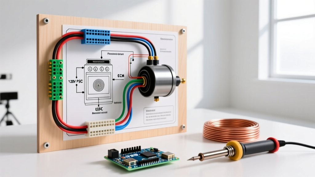
This tutorial bridges standard appliance wiring with specialized motor diagnostics, focusing on the Permanent Split Capacitor (PSC) and Electronically Commutated Motor (ECM) technologies dominating the 2025 and 2026 appliance market. We will explore how to read the schematics, test the windings, and safely execute repairs.
Decoding the 120V Motor Sub-Circuits
Unlike the main bake and broil elements that span L1 and L2 (240V), stove motors operate on a 120V potential derived from either L1 or L2 and the Neutral (N) bus. According to the National Electrical Code (NEC), these branch circuits must be properly protected. While the main range receptacle breaker (typically 40A or 50A) protects the overall unit, internal motors are safeguarded by thermal fuses, inline limiters, and control board relays.
Standard PSC Convection Fan Motors
In mid-tier ranges, the convection fan typically utilizes a shaded-pole or PSC motor. These are robust, inexpensive ($45 to $85 for OEM replacements), and straightforward to wire. The wiring diagram usually shows a direct line from the control board relay, passing through a high-limit thermal fuse (rated around 216°C / 420°F), and terminating at the motor's two spade connectors.
- Wire Gauge: 14 AWG or 16 AWG high-temperature fiberglass-insulated wire.
- Connectors: 187-series or 250-series high-temp female spade connectors with locking tangs.
- Primary Failure Mode: The internal thermal overload switch on the motor housing trips permanently due to grease buildup restricting the fan blade, causing the motor to overheat and open the circuit.
ECM Downdraft and Cooling Motors (2024–2026 Models)
Premium smart ranges introduced in recent years utilize ECMs for downdraft ventilation and internal chassis cooling. ECMs require a constant 120V power supply to the motor's internal inverter, alongside a low-voltage DC signal (usually 5V to 15V) from the main control board to dictate RPM via Pulse Width Modulation (PWM). Furthermore, these motors utilize Hall-effect sensors to provide RPM feedback to the main board. Troubleshooting these requires referencing the specific wiring diagram for stove ECM pinouts; applying 120V directly to the low-voltage signal pins will instantly destroy the main control board.
Step-by-Step Motor Replacement and Wiring Protocol
Critical Safety Warning: Always perform Lockout/Tagout (LOTO) on the main 240V breaker before accessing internal stove wiring. Capacitors in ECM motors and integrated microwave-stove combos can retain lethal charges even when disconnected from the grid.
- Access the Motor Compartment: Remove the rear access panel (typically 1/4-inch hex screws). For convection motors, you may also need to remove the interior baffle plate inside the oven cavity to access the fan blade and mounting nuts.
- Document the Pinout: Before disconnecting, photograph the existing harness. ECM motors often use a 4-pin or 5-pin Molex-style connector where wire color coding varies significantly by manufacturer.
- Inspect the Thermal Limiter: Use a multimeter set to continuity (Ω). Probe the thermal fuse in series with the motor. If it reads 'OL' (Open Line), replace the fuse ($8 to $15) alongside the motor to prevent immediate failure of the new unit.
- Terminate New Connections: If replacing a PSC motor with spade terminals, strip exactly 1/4-inch of the high-temp wire. Use a ratcheting crimp tool to secure the high-temp spade connector. Never use standard vinyl-insulated connectors inside a stove chassis; the ambient heat will melt the insulation and cause a short circuit.
- Verify Grounding: Ensure the motor chassis ground wire (usually green or bare copper) is securely fastened to the unpainted metal frame of the stove to comply with UL safety standards for appliance grounding and fault current dissipation.
Diagnostic Matrix: Motor Symptoms vs. Electrical Faults
| Symptom | Probable Electrical Fault | Multimeter Test & Expected Value | Estimated Repair Cost (2026) |
|---|---|---|---|
| Convection fan hums but does not spin | Failed run capacitor (if equipped) or seized bearing | Test capacitor for microfarads (µF); inspect motor shaft for mechanical binding | $15 (Capacitor) / $75 (Motor) |
| Motor runs for 3 minutes then shuts off | Internal thermal overload tripping due to restricted airflow | Check amp draw; should be under 1.5A. Clean fan blade and housing | $0 (Cleaning) / $75 (Motor if damaged) |
| Downdraft ECM motor completely dead | Loss of 120V constant feed or blown control board triac | Test L1 to Neutral at motor harness: 120V AC. Test signal pins for 5V-15V DC | $220 - $350 (ECM Motor Assembly) |
| Cooling fan runs continuously after stove is off | Stuck relay on main control board or faulty ambient thermistor | Test thermistor resistance at room temp (usually 10kΩ - 50kΩ depending on brand) | $140 - $280 (Control Board) |
Wire Gauge and Circuit Sizing per NEC Standards
When modifying or repairing stove wiring, adhering to the NFPA 70 (NEC) guidelines is non-negotiable. While the internal wiring harness is pre-engineered by the manufacturer, DIY repairs involving splicing or extending motor leads must respect thermal and current limits.
- Internal Motor Leads: Must be minimum 18 AWG for loads under 5A, but 14 AWG is heavily preferred in high-ambient-heat zones (near the broiler or exhaust vents) to prevent voltage drop and insulation degradation.
- Insulation Rating: Standard THHN is insufficient inside the rear chassis of a range. You must use AWM (Appliance Wiring Material) rated for at least 105°C, preferably 150°C or 200°C (Teflon or Fiberglass braid).
- Branch Circuit Sizing: A standard freestanding electric range requires a 40A or 50A, 120/240V dedicated branch circuit using 8 AWG or 6 AWG copper conductors, respectively. The internal motors draw negligible current (typically 0.5A to 2.5A) and do not impact the main breaker sizing, per NEC Article 220.55 demand factor calculations.
- Neutral Bus Handling: Because all 120V motors and control boards return current via the Neutral wire, the neutral conductor in your range cord must be the same gauge as the hot legs (e.g., a 4-wire, 50A range cord uses 6 AWG for L1, L2, Neutral, and Ground).
Expert Troubleshooting FAQ
Why does my stove's convection motor only work on the 'Air Fry' setting but not 'Convection Bake'?
This is rarely a motor issue and almost always a control board logic or relay fault. In modern smart ranges, 'Air Fry' engages the convection motor at a 100% duty cycle via a dedicated high-speed relay, while 'Convection Bake' uses a PWM signal or a secondary relay to run the motor at 60% speed to prevent over-drying food. If one setting fails, trace the specific relay output on the wiring diagram for the stove's main control board to identify the failed switching component.
Can I use a universal 120V AC fan motor to replace an OEM convection motor?
While electrically feasible, it is highly discouraged. OEM motors are specifically balanced for the CFM (Cubic Feet per Minute) requirements of the oven cavity and feature specialized high-temp synthetic grease in the bearings. A universal motor from a hardware store will likely suffer bearing failure within months due to the 200°C+ ambient heat radiating through the rear baffle plate. Always source exact OEM replacements or certified aftermarket equivalents from authorized appliance parts distributors, adhering to NEMA motor standards for appliance applications.
How do I test a 3-speed downdraft exhaust motor?
Older 3-speed PSC downdraft motors feature a common winding and three separate speed windings (High, Medium, Low). Set your multimeter to resistance (Ohms). Measure from the Common terminal to each speed terminal. You should see a progressive increase in resistance (e.g., Common to High = 15Ω, Common to Med = 25Ω, Common to Low = 40Ω). If any reading is infinite (OL), the internal winding is burned out, necessitating a full motor replacement rather than a simple capacitor swap.