
The Physics of High-CFM Fan Current Draw
Upgrading from a mechanical clutch fan to a high-CFM electric setup is one of the most effective ways to reclaim horsepower and stabilize engine temperatures. However, modern high-performance electric fans (such as the Spal 17-inch or Derale 16-inch brushless models) routinely pull between 20A and 35A of continuous current, with inrush spikes exceeding 50A upon startup. Attempting to wire these directly to a toggle switch, OEM thermal switch, or engine control unit (ECU) will result in melted connectors, fried driver transistors, or electrical fires.
A robust radiator electric fan wiring diagram relies on an ISO mini relay to isolate the high-amperage load circuit from the low-amperage control circuit. This step-by-step walkthrough details the exact component selection, wire gauge mathematics, and protective circuitry required for a reliable, fire-safe installation in 2026.
2026 Bill of Materials (BOM) & Component Sizing
Automotive electrical standards require specific materials to withstand under-hood heat and vibration. Do not use standard PVC wire or ATC blade fuses for continuous 30A+ loads. Below is the precise BOM for a single high-draw fan setup.
| Component | Specification / Standard | Purpose | Est. Cost (2026) |
|---|---|---|---|
| Automotive Relay | 40A/50A ISO Mini (e.g., Hella 4RA 003 510-081) | Isolates high-current load from trigger switch | $9.00 - $14.00 |
| Primary Power Wire | 10 AWG GXL or TXL (SAE J1128) | Handles 30A+ continuous load with minimal voltage drop | $1.80 / ft |
| Main Circuit Fuse | 40A MAXI or MIDI Fuse | Protects against dead shorts; resists thermal fatigue | $3.50 |
| Trigger Wire | 14 AWG or 16 AWG GXL | Carries <1A current for relay coil activation | $0.90 / ft |
| Flyback Diode | 1N4001 or 1N4004 (if ECU triggered) | Clamps inductive voltage spikes to protect ECU | $0.15 |
| Terminals | Adhesive-lined heat shrink ring/spade | Prevents moisture intrusion and corrosion at crimps | $6.00 / pk |
Decoding the ISO Mini Relay Pinout
The standard Bosch-style ISO mini relay features four or five pins. For a radiator fan, a 4-pin (Single Pole Single Throw - SPST) relay is ideal. The pin numbers are stamped into the relay housing:
- Pin 30 (Common): High-current power input from the battery.
- Pin 87 (Normally Open): High-current power output to the fan motor.
- Pin 86 (Coil +): Low-current trigger input (12V from ignition or thermal switch).
- Pin 85 (Coil -): Low-current ground for the relay coil.
Expert Note: Pins 85 and 86 are electromagnetically interchangeable on a standard DC relay. However, if your relay has an internal suppression diode or resistor (common in late-model OEM harnesses), polarity matters. Always check the relay schematic printed on the side. For aftermarket Hella or Standard Motor Products relays without internal diodes, 85 and 86 can be reversed safely.
Step-by-Step Radiator Electric Fan Wiring Diagram Walkthrough
Phase 1: The High-Current Load Circuit (Pins 30 & 87)
- Battery Connection & Fusing: Run 10 AWG GXL wire from the positive battery terminal. Within 6 inches of the battery post, install an inline 40A MAXI fuse holder. This protects the entire length of the wire in the event of a chassis short.
- Relay Input (Pin 30): Route the fused 10 AWG wire to Pin 30 on the relay harness. Use a high-quality, adhesive-lined heat shrink ring terminal for the connection.
- Relay Output (Pin 87): Run a second length of 10 AWG wire from Pin 87 directly to the positive terminal of the electric fan motor.
- Motor Grounding: Run a 10 AWG ground wire from the fan's negative terminal to a dedicated chassis ground point. Do not rely on the fan mounting bolts for grounding. Paint, powder coating, and rust will cause severe voltage drop, leading to slow fan speeds and overheated motors.
Phase 2: The Low-Current Control Circuit (Pins 85 & 86)
The control circuit dictates when the fan turns on. This is typically handled by an adjustable thermal switch (e.g., Hayden 3653) threaded into the radiator, or a manual dashboard toggle.
- Ignition Source: Tap into a 12V ignition-switched source (e.g., the AC compressor clutch wire or a dedicated auxiliary fuse panel slot). This ensures the fan cannot run after the engine is turned off, preventing battery drain.
- Thermal Switch Routing: Run 14 AWG wire from the ignition source to one terminal of your thermal switch. Run a second 14 AWG wire from the other thermal switch terminal to Pin 86 on the relay.
- Coil Ground: Run 14 AWG wire from Pin 85 to a clean, bare-metal chassis ground.
Phase 3: ECU Triggers and Flyback Diode Protection
If you are integrating the fan into a modern standalone ECU (like a Holley Terminator X or Haltech Elite), the ECU typically uses a low-side driver. This means the ECU provides the ground to activate the relay, not the 12V power.
- Wiring for Low-Side Driver: Send 12V ignition power to Pin 86. Wire Pin 85 directly to the ECU's designated fan output pin.
- The Flyback Diode Requirement: When the ECU cuts the ground to turn the fan off, the collapsing magnetic field inside the relay coil generates an inductive voltage spike (back-EMF) that can exceed 400V. This spike will instantly destroy the ECU's internal driver transistor. You must solder a 1N4001 diode across Pins 85 and 86.
- Diode Orientation: The silver stripe on the diode must point toward the 12V source (Pin 86). This allows the diode to block normal 12V flow but creates a recirculation loop for the reverse voltage spike, safely dissipating it as heat within the coil.
Thermal Switch vs. PWM Controller Matrix
Choosing the right trigger mechanism impacts both cooling efficiency and electrical noise. Below is a comparison of standard on/off thermal switches versus modern Pulse Width Modulation (PWM) controllers available in the 2026 aftermarket.
| Feature | Standard Thermal Switch (e.g., Derale 16749) | PWM Controller (e.g., Derale 16795 / Spal PWM) |
|---|---|---|
| Operation | Binary (100% On / 100% Off) | Variable speed (20% to 100% duty cycle) |
| Inrush Current | High (50A+ spike on startup) | Low (Soft-start ramping protects alternator) |
| Temperature Stability | Fluctuates (e.g., 195°F to 180°F swings) | Rock solid (Maintains exact target temp) |
| Wiring Complexity | Simple (1 Relay, 1 Switch) | Complex (Requires PWM module, temp sensor) |
| Best Application | Budget builds, carbureted V8s, daily drivers | High-horsepower, tight engine bays, track cars |
Critical Failure Modes & Voltage Drop Testing
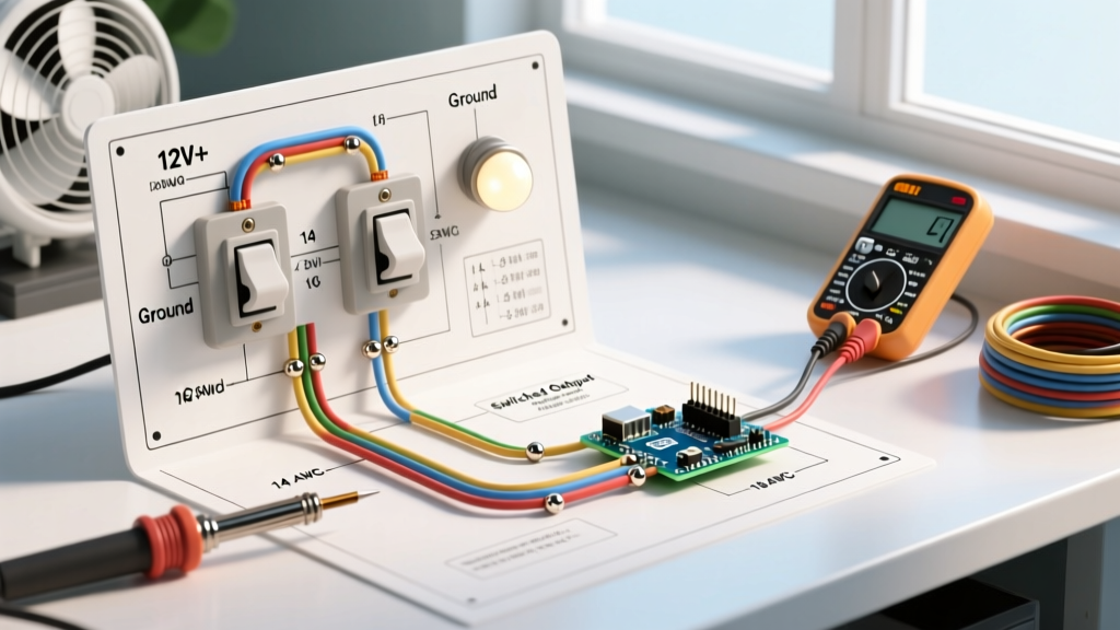
Even with a perfect radiator electric fan wiring diagram on paper, physical installation errors cause 90% of cooling system failures. Use a digital multimeter (DMM) to perform a Voltage Drop Test on the high-current circuit while the fan is running.
How to Perform the Test:
- Set your DMM to DC Volts.
- Place the red probe on the positive battery post and the black probe on the relay Pin 30 terminal. The reading should be less than 0.10V.
- Move the black probe to Pin 87, then to the fan motor positive terminal. Each connection point should add no more than 0.05V of resistance.
- Repeat on the ground side: Red probe on the fan motor casing, black probe on the negative battery post. Total ground side voltage drop must be under 0.20V.
Edge Case - Relay Chatter: If your relay rapidly clicks on and off, you are experiencing voltage drop on the trigger circuit. As the relay coil energizes, it pulls current; if the ignition tap wire is too thin or shares a circuit with high-draw accessories, the voltage drops below the relay's holding threshold, causing it to open. The fix is to run a dedicated 14 AWG trigger wire directly from the ignition fuse panel rather than tapping into an existing sensor harness.
Authoritative References
For deeper diagnostics and standardized testing procedures, consult the following industry resources:
- AA1Car: Automotive Cooling Fan Problems & Diagnostics - Comprehensive troubleshooting for OEM and aftermarket fan circuits, including relay testing and ECU driver verification.
- Littelfuse: Automotive Relay Application Guidelines - Engineering data on contact ratings, inductive load switching, and flyback diode requirements for ISO mini relays.
- AutoShop 101: Automotive Electrical Circuits (PDF) - Foundational mathematics for voltage drop, wire gauge sizing, and relay logic in 12V DC systems.