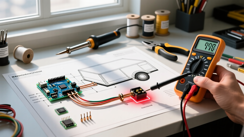

Why a Wiring Diagram is Your Best Diagnostic Tool
When trailer lights malfunction, the instinct for many DIYers is to start swapping bulbs or blindly splicing wires. This approach often leads to chasing ghosts through a tangled harness. The most efficient way to isolate electrical faults is to treat your wiring diagram for a trailer not just as an installation map, but as a diagnostic schematic. By understanding the logical flow of current from the tow vehicle's converter to the trailer's junction box and out to the individual lamps, you can apply systematic troubleshooting methods that save hours of frustration.
According to the SAE International J560 Standard, which governs 7-way electrical connectors for heavy-duty and RV trailers, standardized color codes and pinouts are designed to make circuit isolation predictable. Whether you are working with a simple 4-way flat connector or a complex 7-way RV blade, leveraging the diagram allows you to perform 'half-split' testing, identify phantom voltage, and calculate voltage drop across long harness runs.
Decoding the Standard 7-Way RV Blade Diagram
Before you can troubleshoot, you must understand the baseline architecture. The 7-way RV blade is the most common connector for travel trailers, fifth wheels, and utility trailers equipped with electric brakes. A proper wiring diagram for a trailer will map these circuits by function, color, and required wire gauge.
| Pin Function | Standard Wire Color | Minimum Wire Gauge (AWG) | Common Failure Mode |
|---|---|---|---|
| Left Turn / Stop | Yellow | 14 AWG | Short to ground at tongue hinge |
| Right Turn / Stop | Green | 14 AWG | Corroded bulb socket contacts |
| Tail / Running Lights | Brown | 16 AWG | Overloaded circuit (too many clearance lights) |
| Electric Brakes | Blue | 10 AWG | Voltage drop causing weak braking |
| 12V Auxiliary Power | Black | 10 AWG | Blade fuse failure at tow vehicle |
| Ground Return | White | 10 AWG | Painted grounding surface on trailer tongue |
| Reverse Lights | Red / Purple | 16 AWG | Short circuit blowing reverse fuse |
The 'Half-Split' Troubleshooting Method
In electronics troubleshooting, the half-split method involves testing the circuit at its midpoint to determine which half contains the fault. When using a wiring diagram for a trailer, the physical midpoint is almost always the main junction box or the trailer tongue connector.
Step 1: Isolate the Power Source
Disconnect the trailer from the tow vehicle. Using a dedicated trailer tester (such as the Hopkins 40375 or a similar LED circuit tester), plug it into the tow vehicle's receptacle. Verify that the tow vehicle's converter is outputting 12V to all pins when the respective switches (brakes, turn signals, headlights) are activated. If the tester shows a fault here, the issue is in the tow vehicle, not the trailer. Stop troubleshooting the trailer.
Step 2: Test at the Junction Box
If the tow vehicle is outputting power correctly, reconnect the trailer and locate the main wiring junction box (usually mounted near the tongue). Open the weatherproof cover and use a True-RMS digital multimeter, like the Fluke 115, to probe the terminal blocks.
- Black probe: Attach to the white ground terminal block.
- Red probe: Touch the yellow, green, and brown terminal blocks while an assistant activates the corresponding switches in the tow vehicle.
If you read 12.0V to 12.6V at the junction box but the rear lights are dim or dead, the fault lies in the branch circuits running to the rear of the trailer. If you read 0V at the junction box, the fault is in the main umbilical cord between the plug and the junction box.
Step 3: Trace the Branch Circuits
Consult your wiring diagram to trace the specific color wire from the junction box to the failing lamp. Look for physical choke points where wires are routed through the trailer frame, near suspension components, or inside the rear bumper. These are high-vibration areas where insulation chafes and copper strands break internally, creating an open circuit that a visual inspection will miss.
Common Failure Modes and Diagram-Based Solutions
Phantom Backfeed and Ground Loops
One of the most baffling issues trailer owners face is 'phantom voltage'—for example, the running lights glowing faintly when the brake pedal is pressed, or the turn signals flashing in reverse polarity. A wiring diagram for a trailer reveals why this happens: shared ground paths.
If the dedicated white ground wire (Pin 5 on a 7-way) is compromised, the electrical current will seek an alternative path back to the tow vehicle. It will backfeed through the filaments of other bulbs. For instance, brake current (Yellow/Green) will travel through the brake bulb, into the shared ground at the socket, up through the running light filament (Brown), and back to the tow vehicle. The running light will glow dimly because it is acting as a high-resistance ground path.
Expert Fix: Never rely on the hitch ball for grounding. Use your diagram to locate the main white ground wire and ensure it is secured with a star washer to bare, unpainted steel on the trailer tongue. Apply Permatex 22058 dielectric grease to the connection to prevent galvanic corrosion.
Voltage Drop on Electric Brake Circuits
Electric trailer brakes require significant current, often pulling 3 to 4 amps per brake assembly. On a 25-foot trailer with dual axles, the blue brake wire must travel 50 feet (round trip) from the controller to the furthest brake magnet. If a previous owner used 14 AWG wire instead of the mandated 10 AWG shown on standard diagrams, voltage drop will severely weaken braking performance.
The Math: A 14 AWG copper wire has a resistance of roughly 0.252 ohms per 100 feet. For a 50-foot round trip pulling 12 amps total (four brakes), the voltage drop is V = I × R (12A × 0.126Ω) = 1.51 volts. If your tow vehicle outputs 12.5V, the brake magnets only see 10.99V. Under heavy braking, the controller ramps up to 100% duty cycle, but the magnets are starved of power. Upgrading to 10 AWG wire reduces this drop to less than 0.6V, restoring full braking torque.
Essential Tools for Diagram-Assisted Diagnostics
To effectively execute the troubleshooting steps outlined above, you need the right tools. Guessing with a cheap test light can lead to misdiagnosing modern LED circuits or solid-state converters.
- True-RMS Digital Multimeter: Essential for measuring exact voltage drop and checking continuity on long wire runs. Ensure it has a low-impedance (LoZ) mode to detect phantom ghost voltages caused by capacitive coupling in long parallel wires.
- Wire Tracer / Tone Generator: When the wiring diagram shows a wire disappearing into the trailer's enclosed underbelly or insulation, a tone generator allows you to trace the exact physical route of a specific color wire without tearing apart the interior panels.
- Heat Shrink Butt Connectors: When repairing a broken branch circuit identified via the diagram, never use standard vinyl crimp connectors. Use dual-wall, adhesive-lined heat shrink connectors (e.g., Ancor Marine grade). The heat-activated sealant prevents moisture ingress, which is the number one cause of green corrosion and subsequent open circuits.
Final Thoughts on Schematic Literacy
A wiring diagram for a trailer is more than a color-matching cheat sheet; it is a logical representation of current flow, circuit protection, and load distribution. By combining the schematic with systematic half-split testing and precise multimeter measurements, you can diagnose complex faults like ground loops and voltage starvation in a fraction of the time it takes to blindly replace parts. For comprehensive connector pinouts and vehicle-specific converter guides, referencing resources like the etrailer Comprehensive Wiring FAQ can provide model-specific context to supplement your schematic troubleshooting.