
The Anatomy of the Precedent 48V IQ System
The Club Car Precedent, produced primarily between 2004 and 2018 before transitioning to the Onward and Villager lines, remains one of the most extensively modified light electric vehicles (LEVs) on the market. At its core is the 48V IQ electrical architecture. While the platform is robust, DIY modifications—ranging from lifted suspensions with larger tires to high-draw LED light bars—frequently push the original electrical boundaries. Understanding the wiring diagram for Club Car Precedent models is not just about making components work; it is about preventing thermal runaway, electrical fires, and catastrophic controller failures.
As of 2026, the aftermarket shift toward 48V Lithium Iron Phosphate (LiFePO4) drop-in batteries has altered the load dynamics of these carts. Lithium packs can deliver sustained high-amperage discharge rates that exceed the thermal limits of stock 2 AWG copper cabling if the wiring diagram is not respected and upgraded where necessary. This guide approaches the Precedent wiring schematic strictly through the lens of safety, overcurrent protection, and industry code compliance.
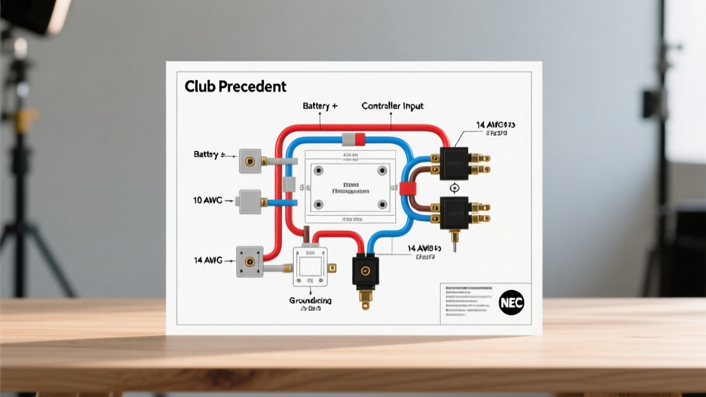
Decoding the Wiring Diagram for Club Car Precedent
The factory wiring schematic for the 48V IQ system revolves around the Curtis 1268 motor controller (or the Toshiba equivalent in later models). To troubleshoot or modify the cart safely, you must understand the three critical safety interlocks built into the diagram:
1. The Solenoid and Pre-Charge Circuit
The main solenoid (typically a 48V, 200A continuous-duty contactor) acts as the primary high-current switch. A critical, often overlooked component in the wiring diagram is the pre-charge resistor (usually 250 ohms, 5W). When the ignition is turned on, a low-current signal passes through this resistor to charge the main capacitors inside the Curtis controller before the heavy solenoid contacts close. Failure Mode: If a DIYer bypasses this resistor to 'fix' a clicking solenoid, the massive inrush current will weld the solenoid contacts shut. The cart will then move forward the moment the F&R switch is engaged, even without pressing the throttle—a severe safety hazard.
2. The MCOR (Motor Controller Output Regulator)
Early Precedent models (2004-2008) utilized the MCOR1 and MCOR2, which relied on physical wiper arms moving across a resistive track. These are notorious for wearing out, causing 'runaway cart' scenarios where the controller reads a false high-voltage signal and applies full throttle. Modern replacements (MCOR3 and MCOR4) use non-contact Hall-effect sensors. When reading the wiring diagram, ensure the 3-pin or 4-pin MCOR harness is routed away from the high-current motor cables to prevent electromagnetic interference (EMI) from inducing ghost voltage signals.
3. The F&R (Forward and Reverse) Microswitches
The F&R switch assembly contains microswitches that dictate the directional logic to the controller. The wiring diagram routes these low-voltage signals (typically 48V stepped down or logic-level 12V/5V depending on the exact controller revision) through the tow/run switch. Always ensure the tow/run switch is in 'TOW' before disconnecting any high-current cables to prevent arcing and controller logic board damage.
Wire Gauge & Overcurrent Protection Matrix
Adhering to proper wire gauging is the first line of defense against electrical fires. The National Electrical Code (NEC) and general LEV safety standards mandate that wiring must handle 125% of the continuous expected load. Below is the required matrix for Precedent 48V systems, factoring in standard 10-foot cable runs and high-torque applications.
| Circuit Path | Stock Wire Gauge | Upgraded/High-Draw Gauge | Required Overcurrent Protection |
|---|---|---|---|
| Battery Pack to Solenoid | 2 AWG | 1/0 AWG (for 600A+ controllers) | Class T Fuse (250A - 400A) |
| Solenoid to Controller (+) | 2 AWG | 1/0 AWG | Protected by Main Class T |
| Controller to Motor (U, V, W) | 2 AWG | 1 AWG (High-Torque Motors) | Controller Internal Logic |
| 48V to 12V Step-Down Converter | 10 AWG | 8 AWG (for 30A+ converters) | Inline ANL or ATO Fuse (40A) |
| Accessory Lighting (12V side) | 14 AWG | 12 AWG | Blade Fuse Block (10A - 15A) |
Safety Callout: Never use standard automotive blade fuses on the main 48V battery positive line. Automotive fuses are rated for 12V-32V DC. Interrupting a 48V DC short circuit with a 32V-rated fuse will result in a sustained plasma arc inside the fuse housing, leading to an immediate fire. Always use DC-rated Class T or ANL fuses.
Critical Safety Violations in DIY Accessory Wiring
When reviewing field modifications against the factory wiring diagram for Club Car Precedent models, our technicians consistently find three major code and safety violations:
- Tapping a Single 12V Battery for Accessories: The 48V pack consists of four 12V (or six 8V) batteries in series. Tapping into just one battery to run 12V headlights or radios causes severe voltage imbalance. This leads to sulfation in the tapped battery and overcharging of the others, drastically reducing the $800-$1,200 battery bank's lifespan and causing hydrogen off-gassing imbalances.
- Undersized Step-Down Converters: Using a cheap, 10A ($15) voltage reducer for a cart equipped with a 20A light bar and a USB charging hub causes the converter to overheat and melt its epoxy casing. Always calculate the total amperage draw and buy a converter rated for 150% of that total (e.g., a 48V-to-12V 30A converter, typically costing $45-$65 from reputable brands like 10L0L or Club Car OEM).
- Missing Main Battery Disconnect: The NEC and general safety guidelines require a readily accessible manual disconnect. Many DIYers wire the main positive cable directly from the battery pack to the solenoid, bypassing the OEM rotary disconnect switch located under the seat. In an emergency or short circuit, first responders or owners have no way to kill power without using insulated tools to unbolt the main cable.
Code Compliance: Charging Infrastructure & ANSI Standards
While the internal wiring of a golf cart is governed primarily by manufacturer specifications and ANSI/OPEI Z135 standards, the charging infrastructure falls under the purview of the National Fire Protection Association (NFPA). According to NFPA 70 (National Electrical Code), specifically Article 625 regarding Electric Vehicle Charging System Equipment, the receptacle used to charge the Precedent must be a dedicated, properly grounded circuit.
For a standard Club Car PowerDrive charger (drawing roughly 12A to 15A at 120V AC), the NEC requires a 20-amp dedicated circuit with a GFCI (Ground Fault Circuit Interrupter) breaker if the receptacle is located outdoors or in a damp garage environment. Furthermore, workplace safety regulations outlined by OSHA for electric-powered industrial trucks mandate that charging areas be adequately ventilated to prevent the accumulation of explosive hydrogen gas emitted during the equalization phase of lead-acid battery charging.
For comprehensive operational safety, including rollover protection and passenger retention systems which indirectly affect how wiring harnesses are routed around structural mounts, refer to the Penn State Extension guidelines on golf cart and utility vehicle safety. Proper harness routing ensures that suspension travel or steering column movement does not chafe against the main wiring loom, a common cause of intermittent ground faults.
Step-by-Step: Safe 12V Accessory Integration
If you are using the wiring diagram to add a 12V accessory (e.g., a horn, underglow, or light bar), follow this compliant integration sequence:
- Disconnect Power: Flip the Tow/Run switch to 'TOW'. Disconnect the main negative cable from the battery pack.
- Install the DC-DC Converter: Mount a 48V-to-12V step-down converter in a dry, ventilated area (avoid the battery compartment due to corrosive sulfuric acid fumes). Connect the 48V input wires to the entire battery pack (Main Positive and Main Negative), not a single battery.
- Install Overcurrent Protection: Place a 40A inline fuse on the 48V positive input wire, within 6 inches of the battery connection point.
- Wire the 12V Distribution Block: Run the 12V output from the converter to a fused marine-grade distribution block. This allows individual accessories to be fused independently (e.g., 5A for a horn, 15A for headlights).
- Grounding Best Practices: Do not daisy-chain ground wires from one accessory to another. Run individual ground wires from each accessory back to the negative bus bar or distribution block to prevent ground loops and voltage drops.
Conclusion
The wiring diagram for Club Car Precedent models is a blueprint for safe, efficient electrical distribution. Whether you are maintaining a stock 2012 IQ cart or upgrading a 2008 model with a modern lithium battery and high-torque motor, respecting wire gauges, utilizing DC-rated overcurrent protection, and avoiding single-battery taps are non-negotiable safety standards. By treating your golf cart with the same electrical rigor as a residential or automotive system, you ensure reliable operation and eliminate the fire hazards that plague poorly executed DIY modifications.