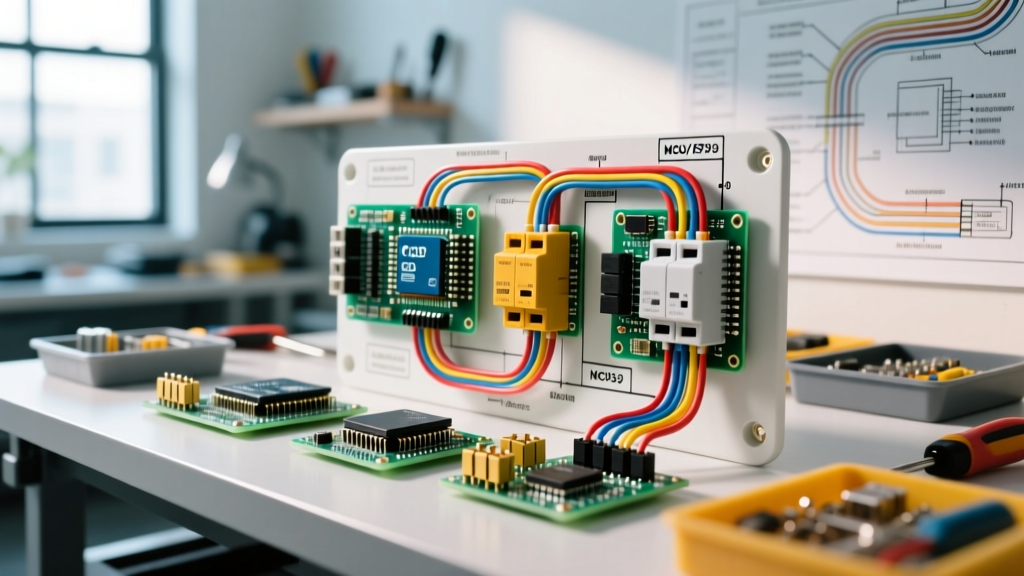

The Critical Role of the Breaker Panel in Mobility Scooters
When analyzing a wiring diagram for mobility scooter electrical systems, the breaker panel serves as the central nervous system for power distribution and safety. Unlike standard automotive 12V systems, modern mobility scooters operate on 24V or 36V DC architectures, routinely pushing 40A to over 100A through the main harness during incline climbs or heavy-load starts. As of 2026, the industry shift toward high-torque brushless DC (BLDC) motors in mid-tier models—such as the Drive Medical Maverick and Pride Mobility Victory 10—has fundamentally altered amperage draw profiles, demanding precise breaker sizing and advanced fuse coordination.
Understanding the panel layout is not just about restoring power after a trip; it is about preventing catastrophic thermal events. According to the U.S. Food and Drug Administration (FDA), electrical malfunctions and battery-related fires remain a primary safety concern for personal mobility devices. This guide provides an expert-level breakdown of scooter breaker panels, circuit routing, and actionable troubleshooting protocols.
Anatomy of the Scooter Breaker Panel
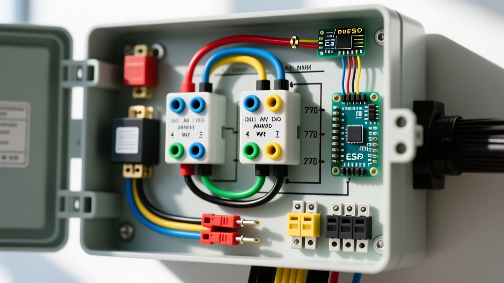
The electrical panel in a mobility scooter is typically housed in a molded ABS plastic shroud near the battery tray or beneath the tiller console. A complete wiring diagram for mobility scooter panels will reveal four primary components:
- Main Circuit Breaker (MCB): Usually a 50A to 100A auto-reset thermal breaker (e.g., Cole Hersee 48059-04). It protects the main battery-to-controller harness from dead shorts.
- Main Power Solenoid: A heavy-duty relay (e.g., White-Rodgers 586-902) that physically connects the battery bank to the motor controller only when the ignition key is turned.
- Shunt Resistor: A low-ohm calibration resistor used by the controller to measure real-time current draw and trigger software-based overcurrent protection.
- Accessory Fuse Block: Houses standard ATC/ATO blade fuses or AGC glass fuses (typically 5A to 15A) for auxiliary circuits like LED headlights, USB charging ports, and tiller displays.
Decoding the Wiring Diagram for Mobility Scooter Circuits
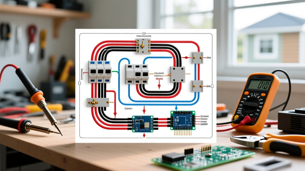
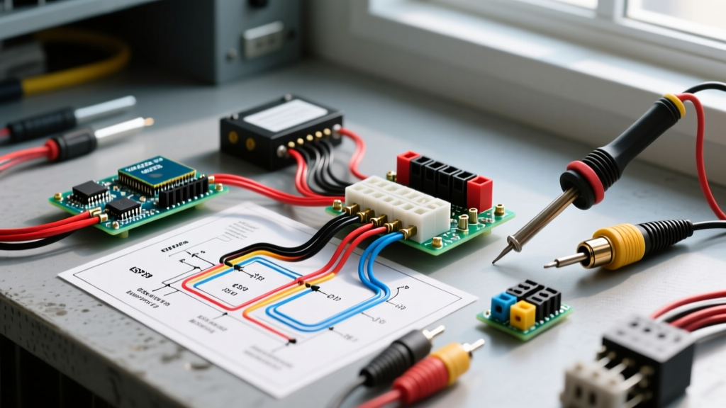
Reading the schematic requires understanding the flow of DC current from the battery bank to the motor controller (such as the ubiquitous Curtis 1228-5300 series). The main positive line (typically Red, 8 AWG) exits the battery pack and immediately passes through the Main Circuit Breaker. From the breaker, it routes to the high-current terminal of the Main Solenoid.
The solenoid's activation coil is fed by a secondary, lighter-gauge wire (often 14 AWG, Orange or Yellow) originating from the ignition switch. When the key turns, the coil energizes, closing the high-current contacts and sending 24V/36V to the B+ terminal on the motor controller. The negative return path (Black, 8 AWG) routes directly from the battery negative to the controller's B- terminal, passing through the shunt resistor for current monitoring.
Standard vs. Proprietary Wire Color Codes
While some manufacturers adhere to standard DC color codes, many utilize proprietary harnesses. Always verify with a multimeter rather than trusting the insulation color blindly.
| Circuit Function | Standard DC Color | Common Proprietary Colors (Pride/Invacare) | Typical Wire Gauge (AWG) |
|---|---|---|---|
| Main Battery Positive (B+) | Red | Red or Brown | 8 AWG to 6 AWG |
| Main Battery Negative (B-) | Black | Black or Blue | 8 AWG to 6 AWG |
| Solenoid Trigger (Ignition) | Yellow/Orange | Orange, Purple, or White/Red tracer | 14 AWG to 16 AWG |
| Motor Phase A/B (Brushed) | Yellow/Blue | Yellow/Green | 10 AWG to 8 AWG |
| Throttle Potentiometer Signal | Green/White | Green, White, Black (3-wire harness) | 18 AWG to 22 AWG |
Breaker and Fuse Sizing Matrix (2026 Standards)
Selecting the correct breaker requires matching the continuous and peak amperage of the motor controller. Undersizing leads to nuisance tripping on mild inclines; oversizing defeats the purpose of the protection, risking harness fires. The UL 2272 Standard for Personal E-Mobility Devices mandates strict coordination between the battery management system (BMS) and external physical breakers.
| Motor Wattage | System Voltage | Continuous Amp Draw | Recommended Main Breaker | Controller Fuse (If Applicable) |
|---|---|---|---|---|
| 250W - 300W | 24V DC | 12A - 15A | 30A Thermal Auto-Reset | 20A AGC Glass |
| 350W - 450W | 24V DC | 18A - 22A | 50A Thermal Auto-Reset | 30A ATC Blade |
| 500W - 650W | 24V / 36V DC | 25A - 35A | 70A Magnetic-Hydraulic | 40A ANL Bolt-Down |
| 800W+ (Heavy Duty) | 36V DC | 40A - 60A | 100A Solid-State / Magnetic | 80A Class T Fuse |
Cost Note: As of 2026, a standard 50A Cole Hersee thermal breaker costs between $14 and $22, while a 100A solid-state smart breaker with Bluetooth fault-logging capabilities ranges from $65 to $95.
Common Panel Failure Modes & Edge Cases
When a mobility scooter loses power, the breaker panel is the first place to investigate. However, the root cause is rarely the breaker itself. Here are the most common failure modes encountered by technicians:
1. Welded Solenoid Contacts (The 'Runaway' Scenario)
If the scooter accelerates the moment the battery is connected—bypassing the ignition key—the main solenoid contacts have likely welded together due to high-current arcing. This happens when the motor draws excessive startup current (often caused by a seized transaxle or damaged motor brushes). Fix: Replace the solenoid immediately and inspect the motor commutator for carbon scoring.
2. Nuisance Tripping Under Load
If the main breaker trips only when climbing a ramp or starting from a dead stop, the issue is usually voltage sag. As AGM batteries age, their internal resistance increases. Under heavy load, the voltage drops significantly, forcing the motor controller to pull higher amperage to maintain wattage (Watts = Volts x Amps). This amperage spike trips a perfectly healthy 50A breaker. Fix: Load-test the battery pack; do not upgrade the breaker size to compensate for weak batteries.
3. Corroded Shunt Resistor Connections
The shunt resistor operates at millivolt levels. Even minor oxidation on the crimp terminals can cause the motor controller to misread the current draw, resulting in erratic speed limiting or complete controller lockout (often flashing a 4-amber-light error code on Pride models). the crimps, apply dielectric grease, and ensure star-washers are biting into bare metal.
Step-by-Step Multimeter Troubleshooting Protocol
Follow this exact sequence to isolate panel faults without risking short circuits. Ensure your multimeter is rated for at least CAT II 600V DC and set to the appropriate DC Voltage or Continuity mode.
- Static Voltage Check: With the scooter OFF, measure voltage directly at the battery terminals. A fully charged 24V system (two 12V AGM batteries) should read between 25.8V and 26.4V. If below 24.0V, charge the batteries before proceeding.
- Breaker Input/Output Test: Measure voltage on the battery side of the main breaker (should match battery voltage). Then measure the load side. If input is present but output is zero, the internal bimetallic strip in the breaker has failed open. Replace the breaker.
- Solenoid Coil Verification: Turn the ignition key to ON. Measure voltage across the solenoid's two small trigger terminals. You should read full battery voltage. If voltage is present but the solenoid does not audibly 'click', the coil is burnt out. Replace the solenoid.
- High-Current Voltage Drop Test: Keep the scooter ON and the rear wheels elevated off the ground. Engage the throttle. Measure the voltage drop across the main breaker and the solenoid contacts. A healthy component will show a voltage drop of less than 0.1V. A drop exceeding 0.3V indicates severe internal resistance and impending failure.
Safety, Compliance, and Maintenance
Adhering to electrical safety standards is paramount when repairing or modifying mobility scooter panels. The Battery University guidelines emphasize that high-current DC systems require specialized crimping tools—never use standard pliers for 8 AWG battery lugs, as poor compression leads to resistive heating and fires. Always use a ratcheting hex-crimp tool and seal the connections with adhesive-lined heat shrink tubing.
Pro-Tip for 2026 Upgrades: If you are maintaining an older brushed-motor scooter, consider upgrading the mechanical thermal breaker to a magnetic-hydraulic breaker. Magnetic-hydraulic breakers trip based on the magnetic field generated by the current, making them completely immune to ambient temperature fluctuations—a common issue for scooters stored in hot garages or used in extreme summer climates.
By thoroughly understanding the wiring diagram for mobility scooter breaker panels, you transition from simply swapping parts to performing true electrical diagnostics. Whether you are servicing a lightweight travel scooter or a heavy-duty all-terrain model, respecting the amperage limits and maintaining clean, tight connections in the breaker panel will ensure years of safe, reliable operation.