
The Legacy and Electrical Quirks of the Farmall Cub
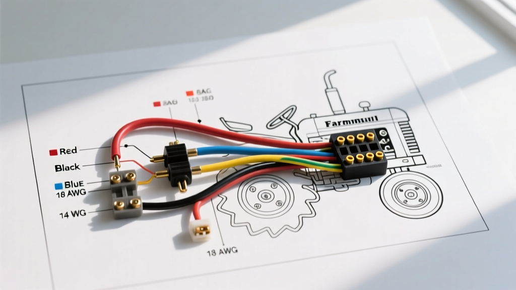
The International Harvester Farmall Cub, produced from 1947 to 1981, remains one of the most iconic compact tractors in agricultural history. However, restoring the electrical system of these machines presents unique challenges. Original factory schematics are notoriously sparse, often depicting simple line drawings with minimal color coding—typically relying on black cloth-covered wires with faint tracer stripes that have long since faded. For modern restorers, relying solely on a 1950s schematic is a recipe for voltage drop, melted insulation, and unreliable starting. To build a reliable harness, you must cross-reference the original wiring diagram for Farmall Cub models with modern automotive electrical standards, specifically focusing on precise wire gauge selection and standardized color codes.
Decoding the Wiring Diagram for Farmall Cub Restorations
When interpreting the factory wiring diagram for Farmall Cub tractors, the first critical decision is whether to retain the original 6-volt system or upgrade to a 12-volt architecture. This decision fundamentally alters your wire gauge requirements and grounding topology.
The 6-Volt vs. 12-Volt Conversion Dilemma
Original 6V Cubs utilized a positive ground system. The battery was located under the seat, and the generator relied on a simple thermal cutout relay rather than a modern voltage regulator. If you maintain the 6V system, you must adhere to positive grounding and use heavier gauge wires to compensate for the higher amperage required to deliver the same wattage. Conversely, a 12V conversion—which is highly recommended if you are adding modern implements, LED lighting, or electronic ignition modules like the PerTronix Ignitor—requires flipping the system to a negative ground. This is mandatory because modern 12V alternators (such as the ubiquitous Delco 10-SI) and solid-state accessories are engineered exclusively for negative ground chassis.
Wire Gauge Selection: Beating Voltage Drop
The most common mistake in tractor restoration is using 12-volt wire gauge standards for a 6-volt system. According to principles outlined in the National Electrical Code (NEC), voltage drop is a function of current (amperage), wire length, and conductor cross-sectional area. Because a 6V system requires twice the amperage of a 12V system to produce the same power (Watts = Volts x Amps), the wire must be significantly thicker to prevent the voltage from dropping below the threshold required to engage the starter solenoid.
For the Farmall Cub, the battery is located roughly 4 to 5 feet away from the starter motor, mounted low on the engine block. This extended run exacerbates voltage drop. The formula for voltage drop is VD = (2 x K x I x L) / CM, where K is the resistivity of copper (12.9), I is current, L is length, and CM is circular mils of the wire.
Farmall Cub Wire Gauge Specification Table
| Circuit | Original 6V AWG (Min) | 12V Conversion AWG | Max Estimated Amp Draw | Notes & Edge Cases |
|---|---|---|---|---|
| Battery to Starter | 1/0 AWG (or 2 AWG) | 4 AWG | 150A - 180A (Cranking) | Use fine-stranded welding cable for flexibility around the engine block. |
| Battery to Ammeter | 10 AWG | 12 AWG | 35A (Generator output) | Early Cubs use a shunt-style ammeter; ensure terminals are tightened to 15 in-lbs. |
| Ammeter to Ignition | 12 AWG | 14 AWG | 4A - 6A | Route away from exhaust manifold; use high-temp GXL wire. |
| Ignition to Coil | 14 AWG | 16 AWG | 3A | If using an external ballast resistor for 12V, wire must handle initial surge. |
| Lighting Circuit | 12 AWG | 14 AWG | 10A (Halogen) / 2A (LED) | Upgrade to 12 AWG if adding modern 55W halogen work lights. |
Implementing Modern SAE Color Codes
Original International Harvester wiring diagrams rarely specified distinct colors for every circuit, leading to confusing, monochromatic harnesses. For safety, troubleshooting, and adherence to the SAE J1128 Standard for low-tension automotive wire, modern restorations should implement a strict color-coded matrix. This ensures that any future mechanic or owner can trace a fault without needing to decipher faded 70-year-old cloth insulation.
- Red: Unswitched battery power (Battery to Ammeter, Ammeter to Starter solenoid, direct accessory feeds).
- Black: Chassis ground returns (in a negative ground 12V system) or primary power feeds (in a positive ground 6V system).
- Yellow: Switched ignition power (Ignition switch output to coil and accessories).
- Blue: High-beam headlight circuit.
- Green: Low-beam headlight circuit and turn signal indicators (if added).
- Brown: Tail lights, panel illumination, and license plate lights.
- White: Instrument cluster illumination and grounding wires for specific isolated sensors.
Step-by-Step Harness Fabrication
Building a custom harness from scratch using a modernized wiring diagram for Farmall Cub layouts requires specific materials to survive the harsh, high-vibration, high-heat environment of a single-cylinder or twin-cylinder tractor engine.
- Select the Right Wire Insulation: Do not use standard PVC-insulated (GPT) wire near the engine. PVC becomes brittle and melts at temperatures above 90°C (194°F). Instead, purchase SAE GXL wire, which features cross-linked polyethylene insulation rated for 125°C (257°F) and offers a thinner outer diameter, making it easier to route through tight firewall and dash gaps.
- Cutting and Looming: Cut your wires 15% longer than the measured route to allow for service loops. Bundle the wires using non-adhesive split loom tubing (3/8-inch or 1/2-inch diameter) and secure it with high-temperature friction tape (like Tesa 51036) rather than zip-ties, which can saw through insulation under engine vibration.
- Terminal Crimping: Abandon cheap stamped-metal terminals. Use adhesive-lined, 3:1 heat-shrink ring terminals. The adhesive melts during the heating process, sealing out moisture and preventing the green corrosion that plagues outdoor agricultural equipment. Use a ratcheting crimping tool (such as the Titan 11477 or Astro Pneumatic 4508) to ensure a gas-tight mechanical bond.
- Routing and Securing: Route the harness along the steering torque tube and frame rails, avoiding the exhaust manifold and steering gear linkages. Secure the loom every 8 to 10 inches using stainless steel cushion clamps (Adel clamps) bolted to existing frame holes.
Common Failure Modes and Edge Cases
Even with a perfect wiring diagram for Farmall Cub tractors, restorers frequently encounter specific edge cases that cause electrical failures:
The Ammeter Shunt Melt
Early Farmall Cubs routed the entire generator output and battery charging current through the dashboard ammeter. If the connections on the back of the ammeter become loose, the increased resistance generates massive heat, often melting the plastic dash panel or causing a fire. Solution: Always clean the ammeter studs with a wire wheel, apply a thin layer of dielectric grease, and torque the nuts precisely. If upgrading to a high-output 12V alternator (e.g., 60+ amps), bypass the original ammeter with a heavy-gauge shunt wire and install a modern digital voltmeter instead.
Ignition Switch Terminal Fatigue
The original 4-position ignition/light switches used on Cubs are notorious for internal contact wear. When the internal resistance increases, the voltage reaching the ignition coil drops below the 5.5V threshold required to sustain a strong spark under load, causing the tractor to stall when the PTO is engaged. Upgrading to a heavy-duty Cole Hersee rotary switch (Part #55034) rated for 35 amps resolves this bottleneck.
Expert Troubleshooting Tip: Never rely on the tractor's painted chassis for critical grounding. The Farmall Cub's engine block is mounted to the frame via rubber vibration isolators on some later models, and layers of grease and rust act as insulators. Always run a dedicated 10 AWG braided copper ground strap directly from the engine block to the negative battery terminal (or chassis ground stud) to ensure the starter motor completes its circuit efficiently.
By combining the historical layout of the original wiring diagram for Farmall Cub machines with modern SAE color codes, high-temperature GXL wiring, and mathematically sound gauge selections, you can build an electrical system that is not only safer but significantly more reliable than the day it rolled off the assembly line in Louisville, Kentucky. For further safety protocols regarding agricultural machinery modifications, always consult the OSHA Agricultural Safety Guidelines to ensure your workshop practices meet current industry standards.