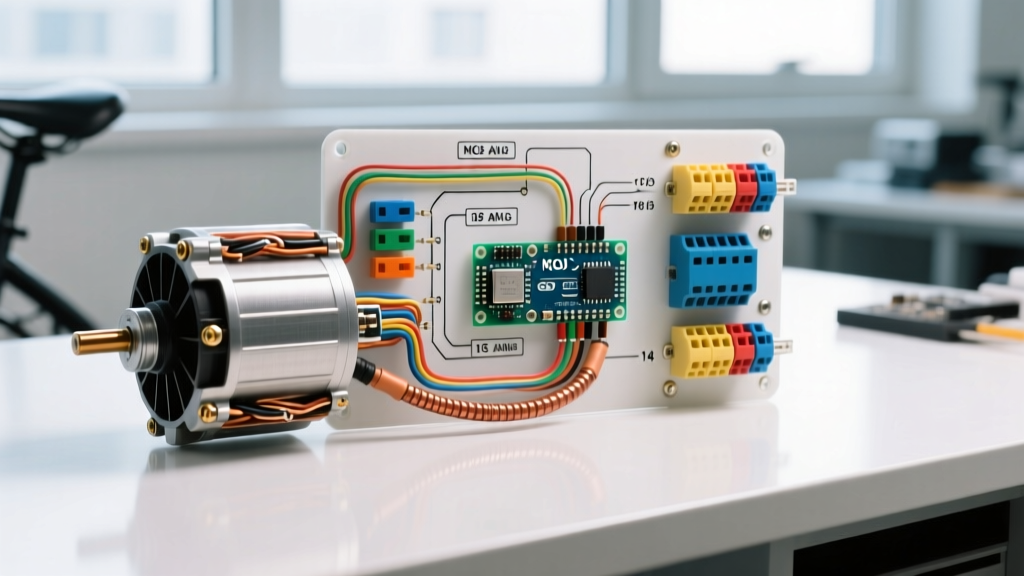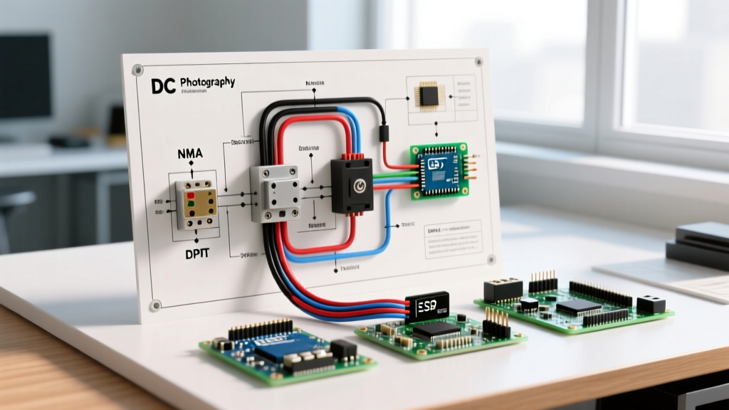

Decoding the DC Electric Motor Wiring Diagram
Interpreting a DC electric motor wiring diagram requires more than just connecting positive and negative terminals. Whether you are wiring a 12V permanent magnet motor for a robotics project or a 240V shunt-wound industrial motor for a lathe, understanding the internal topology is critical. Incorrect wiring in DC circuits doesn't just cause a tripped breaker; it can lead to catastrophic 'runaway' conditions, severe inductive voltage spikes, and immediate armature burnout.
This reference guide breaks down standard NEMA terminal markings, explains the wiring logic for different motor topologies, and provides actionable diagrams for reversing and Pulse Width Modulation (PWM) speed control.
NEMA Standard Terminal Markings
Before touching a wire stripper, you must identify the terminals. The National Electrical Manufacturers Association (NEMA) standard MG-1 dictates specific alphanumeric codes for DC motor leads. Misidentifying a shunt field lead as an armature lead is a common and destructive error. According to the NEMA MG-1 Standard, the following designations apply to standard industrial DC motors:
| Terminal Code | Component | Function & Wiring Notes |
|---|---|---|
| A1, A2 | Armature | Carries the main load current. Reversing A1/A2 swaps rotation direction. Requires heavy-gauge wire (e.g., 10 AWG for 30A). |
| F1, F2 | Shunt Field | High resistance, low current winding. Must be energized before or simultaneously with the armature to prevent runaway. |
| S1, S2 | Series Field | Low resistance, high current winding. Wired in series with the armature. Provides high starting torque. |
| B1, B2 | Interpole / Compensating | Used in large motors to reduce armature reaction and sparking at the brushes. Wired in series with A1/A2. |
Core DC Motor Configurations and Wiring Logic
The topology of your motor dictates how the wiring diagram is structured. As detailed in foundational electrical engineering texts like the All About Circuits DC Textbook, there are three primary wound configurations, plus the ubiquitous permanent magnet variant.
1. Permanent Magnet DC (PMDC)
The simplest diagram. PMDC motors use permanent magnets for the stator field. Wiring consists of two leads (usually red and black). Reversing polarity reverses direction. Speed is directly proportional to applied voltage. These are standard in 12V/24V automotive and hobby applications.
2. Shunt-Wound DC Motor
In a shunt motor, the field winding (F1, F2) is wired in parallel (shunt) with the armature (A1, A2). Wiring Rule: The shunt field must never be opened while the motor is running. If the F1-F2 circuit breaks, the magnetic field collapses, Counter-Electromotive Force (CEMF) drops to zero, and the armature draws massive current, accelerating uncontrollably until mechanical disintegration occurs.
3. Series-Wound DC Motor
The series field (S1, S2) is wired in series with the armature. Wiring Rule: Never run a series motor without a mechanical load. Without load resistance, the motor will 'run away' due to the dropping current weakening the series field. These are heavily used in traction applications (e.g., golf carts, forklifts) where high starting torque is required.
4. Compound-Wound DC Motor
Combines both shunt and series windings. The standard 'cumulative compound' wiring diagram connects the series field so its magnetic flux aids the shunt field. This provides the high starting torque of a series motor with the safe, no-load speed regulation of a shunt motor.
Reversing a DC Motor: The DPDT Switch Diagram
To reverse a DC motor, you must reverse the current flow through either the armature or the field winding, but never both simultaneously. Reversing both results in the same rotational direction.
Pro-Tip for Industrial Wiring: It is standard industry practice to reverse the armature (A1, A2) rather than the shunt field. The shunt field is highly inductive; interrupting and reversing it can generate massive voltage spikes that degrade switch contacts and insulation.
Step-by-Step DPDT Reversing Circuit
For manual control under 20A, a Center-Off Double-Pole Double-Throw (DPDT) toggle switch is the most reliable method.
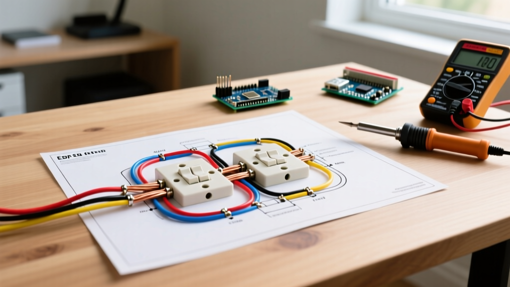
- Step 1: Connect the main DC positive supply to the center terminal of Pole 1, and DC negative to the center terminal of Pole 2.
- Step 2: Wire the top-left and bottom-right terminals together (Cross-wire A).
- Step 3: Wire the top-right and bottom-left terminals together (Cross-wire B).
- Step 4: Connect Motor Terminal 1 to the top-middle (output) terminals, and Motor Terminal 2 to the bottom-middle output terminals.
- Step 5: When toggled UP, current flows straight through. When toggled DOWN, the cross-wires swap the polarity at the motor terminals.
Integrating PWM Speed Controllers
For precise speed control without the massive heat loss of rheostats, Pulse Width Modulation (PWM) is required. When wiring a PWM controller (such as the popular Cytron MD30C 30A controller) into your DC electric motor wiring diagram, specific attention must be paid to the logic vs. power grounds.
PWM Wiring Checklist
- Power Stage: Connect heavy-gauge battery leads to the controller's VIN and GND terminals. Keep these leads as short as possible to minimize parasitic inductance.
- Motor Stage: Connect the controller's M1 and M2 terminals directly to the motor's A1 and A2.
- Logic Stage: Wire your microcontroller (e.g., Arduino, ESP32) PWM output pin to the controller's PWM input. Crucial: The microcontroller GND must be tied to the controller's Logic GND to establish a common reference voltage.
Critical Safety: Flyback Diodes and Inductive Kickback
DC motors are massive inductors. When you cut power to a DC motor (especially via a PWM signal switching at 20kHz), the collapsing magnetic field generates a reverse voltage spike that can easily exceed 100V on a 12V system. This will instantly destroy MOSFETs in your speed controller.
The Fix: Your wiring diagram must include a flyback (freewheeling) diode. Solder a fast-recovery diode (like the UF4007 or a Schottky diode like the 100V/10A 10TQ045) in reverse parallel across the motor terminals. The cathode (stripe) faces the positive supply, allowing the spike to recirculate safely back into the circuit. Many modern controllers have these built-in, but verifying their presence with a multimeter diode-test mode is a mandatory best practice.
Troubleshooting Matrix: Faults and Edge Cases
When your wiring doesn't perform as expected, use this diagnostic matrix based on common field failures documented by Electrical4U and industrial maintenance logs.
| Symptom | Probable Wiring Fault | Diagnostic Action |
|---|---|---|
| Motor spins uncontrollably fast (Runaway) | Shunt field (F1/F2) circuit is open or wired with too high a resistance. | Measure F1-F2 resistance. It should be high (e.g., 50-200 ohms) but continuous. Check for blown field fuses. |
| Motor hums, draws high current, but won't turn | Armature (A1/A2) is shorted, or mechanical seizure. In PMDC, demagnetized stator. | Disconnect power. Spin shaft manually. Measure A1-A2 resistance; should be very low (under 2 ohms) but not zero. |
| Motor runs in reverse of expected direction | Polarity swapped on both Armature and Field, or PMDC leads reversed. | Swap ONLY the A1 and A2 leads. Leave the field wiring untouched. |
| Severe sparking at the brush commutator | Interpole winding (B1/B2) disconnected or wired in opposition to the armature. | Verify B1/B2 continuity. Ensure interpole flux opposes the armature flux in the direction of rotation. |
Wire Gauge and Overcurrent Protection
Finally, a wiring diagram is incomplete without specifying conductor sizing and protection. DC systems suffer from significant voltage drop compared to AC. According to NEC Table 310.16, while 14 AWG copper is rated for 15A, a 12V DC motor drawing 15A over a 10-foot run will experience a 3% voltage drop, robbing the motor of torque. Always oversize DC conductors by at least one AWG step compared to equivalent AC charts, and use Class-T or ANL fuses within 7 inches of the battery positive terminal to protect against high-current DC arcing faults.