
The Electromechanical Anatomy of a Pre-Lit Tree
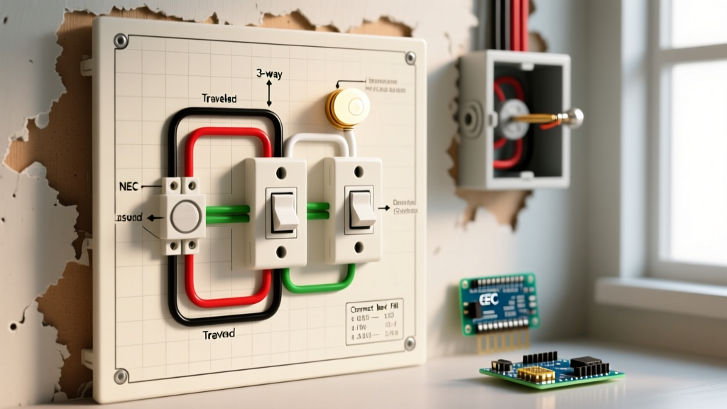
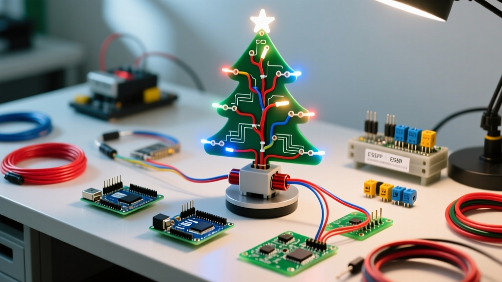
When enthusiasts and technicians search for a wiring diagram for pre lit Christmas tree systems, they are often unprepared for the complexity hiding beneath the artificial pine needles. While most consumers view these holiday centerpieces as simple decorations, an electrical engineer sees a sophisticated parallel-wired AC/DC hybrid circuit integrated with a synchronous rotation motor. As of the 2025 and 2026 holiday seasons, premium manufacturers like National Tree Company, Balsam Hill, and Trimble Home have largely transitioned to smart-triac foot pedals and low-voltage 24V DC LED drivers, making the electrical topology significantly more complex than the simple series-wired incandescent trees of the early 2000s.
Treating your holiday display with the rigor of a motor wiring tutorial is the most effective way to diagnose rotational failures, dead light branches, and tripped GFCI breakers. In this comprehensive guide, we will deconstruct the internal wiring harness, detail the synchronous motor specifications, and provide a step-by-step framework for splicing, repairing, and upgrading your tree's electrical backbone.
Core Components: The Synchronous Motor and Lighting Branches
Before tracing the wiring diagram, you must understand the two primary electrical loads operating in parallel within the tree's central trunk: the lighting branches and the rotating base motor.
1. The Synchronous AC Rotation Motor (TYD-50 / 49TYJ Series)
Most motorized tree stands utilize a 120V AC, 60Hz, 4W to 6W synchronous motor, commonly identified by model numbers like TYD-50 or 49TYJ. These motors are chosen for their high starting torque and ability to maintain a precise, constant speed (usually 1 to 2 RPM after internal gear reduction) regardless of the load weight of the tree.
- Coil Resistance: Typically measures between 1.5kΩ and 2.5kΩ across the main windings.
- Phase Shifting: To achieve continuous unidirectional rotation from a single-phase AC supply, these motors rely on a phase-shifting capacitor (usually 0.15µF to 0.22µF, rated at 250VAC). This capacitor is often housed inside the foot pedal controller rather than the motor housing itself.
- Gear Reduction: The motor shaft drives a multi-stage nylon spur gear assembly. A common failure mode is the stripping of the final nylon gear, resulting in a motor that hums and draws current but fails to rotate the tree.
2. The Low-Voltage LED Lighting Branches
Modern pre-lit trees utilize 24V or 31V DC LED strings. The main trunk contains a heavy-gauge power distribution harness that steps down the 120V AC wall power via a plug-in switching transformer (rectifier). The branches connect to the trunk via 4-pin or 5-pole color-coded quick-disconnects. Because LEDs are polarity-sensitive, reversing the branch connectors will result in a completely dark section, a common point of confusion during post-assembly troubleshooting.
Step-by-Step Wiring Diagram for Pre Lit Christmas Tree Integration
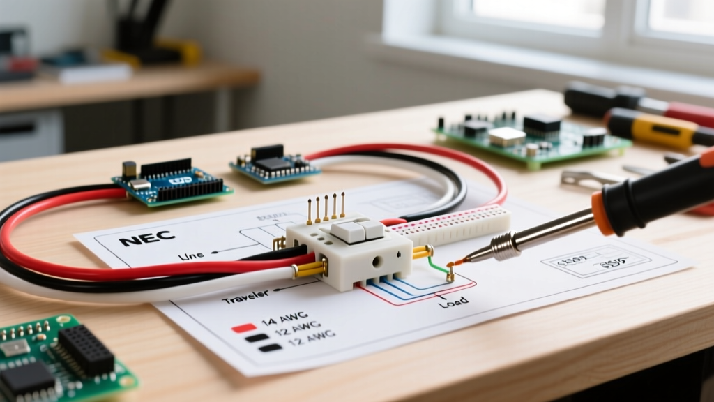
If you are rebuilding a tree harness, replacing a burnt-out foot pedal, or integrating an aftermarket rotating base, follow this motor-wiring-level schematic approach.
Phase 1: Main Power Entry and Foot Pedal Switch
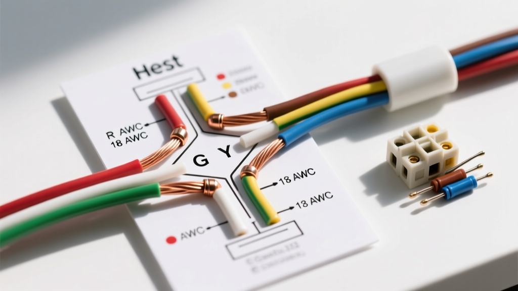
The power entry utilizes 18 AWG SPT-1 (Spatial Parallel Thermoplastic) zip cord, standard for lightweight indoor appliances. The foot pedal in modern 2026 models is not a simple SPST (Single Pole Single Throw) switch. It is a multi-function PCB enclosure containing:
- A TRIAC Dimmer Circuit: Controls the pulse-width modulation (PWM) or phase-angle firing for the LED lighting branches, allowing for dimming or multi-function chasing effects.
- A Motor Relay or Direct Pass-Through: Supplies unswitched 120V AC to the synchronous motor, often routing through the aforementioned phase-shift capacitor.
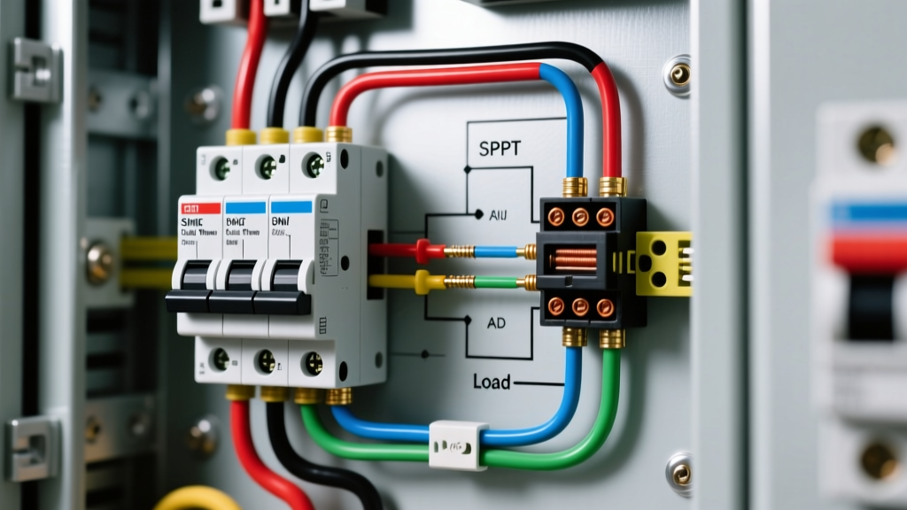
Wiring Step: Splice the hot (black) wire from the SPT-1 cord to the input terminal of the foot pedal PCB. The neutral (white) wire should bypass the pedal's switching logic and wire directly to the common neutral bus of the tree's main trunk harness. This ensures the motor always receives a complete neutral return path, preventing dangerous floating voltages.
Phase 2: Splicing the Rotating Motor Branch
The rotating motor must be wired in parallel with the main lighting trunk, but it should be physically isolated from the flexible branch hinges to prevent wire fatigue. Route the 20 AWG motor lead wires up through the center PVC pole of the bottom tree section.
Expert Tip: Never wire the synchronous motor in series with the LED driver. The motor requires a pure 120V AC sine wave to generate the correct rotating magnetic field. Feeding it modified AC or DC will cause immediate coil burnout and present a severe fire hazard.
Phase 3: Branch Light Circuit Splicing
When repairing a damaged branch harness, use 22 AWG stranded copper wire. Strip exactly 3/8 inch of insulation and use heat-shrink butt connectors with integrated solder rings. Standard electrical tape will dry out, lose adhesion, and expose live 24V DC contacts within a single holiday season due to the ambient heat generated by the LED clusters.
Troubleshooting Matrix: Motor Hum, Dead Lights, and Tripped GFCIs
Use this diagnostic matrix to isolate faults using a standard digital multimeter (DMM). Always ensure the tree is unplugged before performing continuity or resistance tests.
| Symptom | Multimeter Reading | Root Cause Analysis | Corrective Action |
|---|---|---|---|
| Motor hums loudly, tree does not rotate | Motor coil reads ~2kΩ; Voltage at plug is 120V AC | Internal nylon reduction gear teeth are stripped, or the permanent magnet rotor is seized. | Replace the TYD-50 motor assembly (Cost: $18-$25). Do not attempt to reglue nylon gears. |
| Motor spins erratically or reverses direction | Capacitor reads shorted or infinite resistance (OL) | The phase-shifting capacitor in the foot pedal has failed, eliminating the directional magnetic bias. | Solder in a replacement 0.15µF 250VAC metallized film capacitor. |
| Entire tree lighting is dead, motor spins fine | 0V DC at the output of the plug-in LED transformer | Blown rectifier diode or failed switching MOSFET inside the low-voltage LED driver brick. | Replace the 24V/31V DC LED driver. Ensure the replacement matches the exact DC output and amperage (usually 1.5A to 2.0A). |
| One specific tree branch is completely dark | 24V DC present at trunk receptacle, 0V at branch end | Broken internal copper trace on the branch PCB, or reversed polarity connection at the quick-disconnect. | Flip the branch plug 180 degrees. If still dead, trace the branch wire for a physical pinch-point break near the hinge joint. |
| GFCI breaker trips immediately upon plugging in | Low resistance (<50Ω) between Hot and Ground wires | Insulation breach in the SPT-1 main cord, or moisture ingress into the foot pedal PCB enclosure. | Discard the compromised cord/pedal. Replace with a UL-listed 18 AWG SPT-1 replacement cord set. |
Wire Gauge, Shunts, and Safety Standards
Electrical safety is paramount when dealing with combustible artificial foliage. According to the National Fire Protection Association (NFPA), electrical failures or malfunctions are the leading causes of holiday decoration fires. Furthermore, the U.S. Consumer Product Safety Commission (CPSC) strictly monitors seasonal products under UL Standard 588 (Standard for Seasonal and Holiday Decorative Products).
When modifying or repairing your tree's wiring diagram, you must adhere to these non-negotiable safety parameters:
- Wire Gauge: Never downgrade the main trunk harness. If the factory uses 18 AWG, your replacement must be 18 AWG or thicker (e.g., 16 AWG). Branch wiring can utilize 20 or 22 AWG, provided the run length does not exceed 4 feet to prevent voltage drop.
- Overcurrent Protection: Modern LED transformers include an internal thermal fuse. If you are bypassing a factory transformer to wire in a custom smart-plug setup, you must install an inline 3A fast-blow glass fuse on the 120V AC hot leg to prevent catastrophic wire melting in the event of a short circuit.
- Strain Relief: All wiring entering the foot pedal or the base of the metal tree pole must be secured with a rubber grommet and a cable tie to prevent the sharp metal edges from shearing the SPT-1 insulation over time.
Frequently Asked Questions (FAQ)
Can I use a standard household dimmer switch for my pre-lit tree?
No. Standard household incandescent dimmers use TRIAC phase-cutting designed for 120V AC resistive loads. If your tree uses a low-voltage DC LED transformer, a standard dimmer will cause the transformer's switching power supply to buzz violently, overheat, and eventually fail. You must use a dimmer specifically rated for low-voltage electronic transformers (ELV), or rely on the factory-provided foot pedal.
Why does my rotating tree stand motor get hot to the touch?
Synchronous AC motors like the TYD-50 are designed to run warm. The coil housing can safely reach temperatures up to 140°F (60°C) during continuous operation. However, if the motor casing is too hot to touch, or if you smell melting plastic, the internal rotor may be mechanically bound, causing the coil to draw locked-rotor current. Unplug the tree immediately and check for debris wrapped around the central rotation shaft.
How do I identify the correct replacement plug for my tree branches?
Manufacturers use proprietary pin configurations to prevent consumers from mixing 24V and 31V systems. Look for the UL holographic sticker on the factory transformer, which will list the exact DC output voltage and the manufacturer (e.g., Changzhou Jinxu or Foshan Power). Match the replacement branch connectors not just by pin count (4-pin vs 5-pin), but by the physical keying notch on the plastic housing.