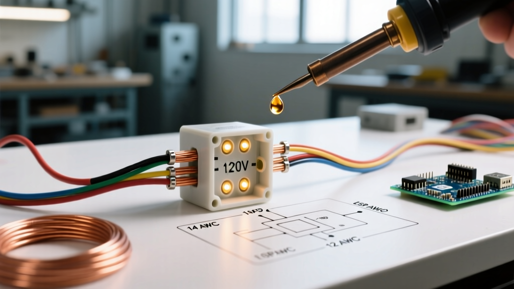

The Modern Recessed Light: An Integrated Appliance
When discussing residential and commercial illumination, the term 'appliance' might not immediately bring lighting to mind. However, under the National Electrical Code (NEC), a luminaire is treated as an electrical appliance that requires dedicated hardwiring, proper grounding, and strict adherence to box-fill and thermal regulations. Today's market has almost entirely shifted away from traditional metal 'can' housings toward integrated, canless LED modules. These units feature an attached, sealed junction box that houses the LED driver, effectively turning the entire recessed light into a self-contained appliance.
Understanding the wiring diagram for recessed lighting is no longer just about connecting a simple socket; it involves interfacing with solid-state LED drivers, managing daisy-chain load limits, and ensuring compatibility with smart home ecosystems. Whether you are installing the highly rated Halo HLB6 series or the Lithonia WF6 ultra-thin panels, the fundamental 120V AC wiring principles remain identical. This guide provides a master-level tutorial on reading, interpreting, and executing these wiring diagrams safely and efficiently in 2026.
Decoding the Wiring Diagram for Recessed Lighting
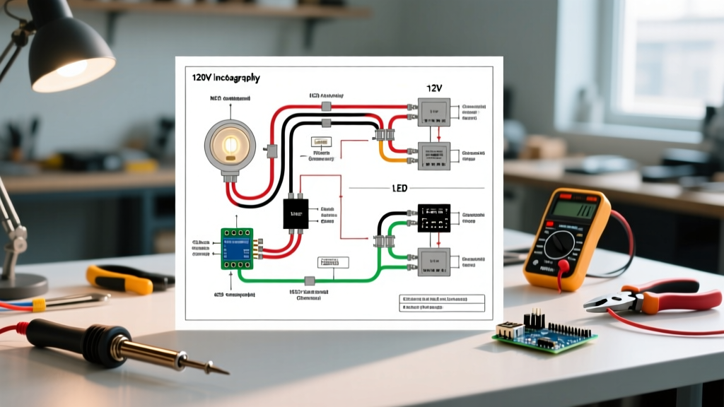
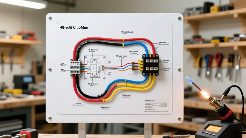
A standard residential recessed lighting circuit operates on a 120V, single-phase alternating current (AC) system. The wiring diagram for a daisy-chained recessed lighting run involves three primary conductors, plus a ground. Below is the schematic breakdown of how power flows from the breaker panel, through the wall switch, and into the integrated LED junction boxes.
Pro Tip: Always treat the attached junction box on a canless LED as a standard NEC-compliant enclosure. Do not attempt to open the sealed driver compartment, as this voids the UL listing and compromises the IC (Insulation Contact) rating.
The Conductor Mapping
- Line (Hot / Black): Carries the unswitched 120V AC current from the breaker panel to the switch loop, or from the switch back to the first luminaire (switched hot).
- Neutral (White): Completes the circuit back to the panel. In modern smart-switch setups, a dedicated neutral wire at the switch location is mandatory to power the switch's internal Wi-Fi/Zigbee radio.
- Ground (Bare Copper / Green): The safety fault path. Must be bonded to the junction box's internal grounding screw or pigtail.
- Load (Switched Hot / Red or Black): The conductor carrying power from the switch to the first light fixture, and subsequently daisy-chained to downstream fixtures.
Daisy-Chain Schematic Flow
When wiring multiple recessed lights on a single switch, you are creating a parallel circuit. The wiring diagram dictates that the incoming power (Line and Neutral) enters the first junction box. From there, a second set of conductors (Load and Neutral) exits the same box to feed the second fixture, and so on. The Wago 221 series lever connectors are the industry standard for these nodes, allowing up to three wires (1 incoming, 1 outgoing, 1 fixture pigtail) to be securely terminated without the risk of loose wire-nut pigtails.
Wire Gauge and Circuit Load Matrix
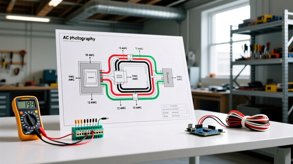
Sizing your breaker and wire gauge correctly is critical. While LED recessed lights draw minimal wattage (typically 9W to 15W per fixture), the NEC mandates strict limits on continuous loads and voltage drop over long runs. According to the National Fire Protection Association (NFPA 70), lighting circuits in dwelling units must be calculated based on the maximum potential load.
| Breaker Size | Wire Gauge (Copper) | Max Continuous Load (80% Rule) | Theoretical Max Fixtures (at 12W each) | Practical Run Limit (Voltage Drop) |
|---|---|---|---|---|
| 15 Amp (AFCI) | 14 AWG | 1,440 Watts | 120 Fixtures | ~50 ft total run length |
| 20 Amp (AFCI) | 12 AWG | 1,920 Watts | 160 Fixtures | ~75 ft total run length |
Note: While the theoretical math allows for over 100 fixtures on a 15A breaker, practical installation limits are dictated by voltage drop (keeping it under 3%) and the physical box-fill capacity of the first junction box in the daisy chain. Most professional electricians cap a single residential lighting circuit at 8 to 12 recessed fixtures to ensure optimal dimmer performance and prevent inrush current tripping.
Step-by-Step Hardwiring Tutorial
Executing the wiring diagram requires precision and the right tools. Follow this step-by-step procedure to ensure a safe, code-compliant installation.
Step 1: Verification and Prep
Shut off the 15A or 20A AFCI breaker at the main panel. Use a non-contact voltage tester (such as the Klein Tools NCVT-3) to verify zero voltage at the junction box. Strip the outer NM-B (Romex) jacket back exactly 3/4 of an inch using a dedicated cable ripper to avoid nicking the inner insulation. Strip the individual conductors to 11mm (7/16 inch) to match the strip gauge on Wago 221 lever nuts.
Step 2: Grounding First
Always connect the bare copper ground wires first. If the LED junction box has a green grounding screw, create a pigtail using a crimp ring terminal. Connect the incoming ground, the outgoing ground (if daisy-chaining), and the box pigtail together. This ensures that if a fault occurs during the rest of the wiring process, the safety path is already established.
Step 3: Neutral Terminations
Connect all white neutral wires together. In a standard 3-way or single-pole switch loop, the neutrals bypass the switch and connect directly from the panel to the light fixtures. Use a 3-port or 5-port Wago lever nut. Ensure no bare copper is exposed outside the connector housing.
Step 4: Hot / Switched Hot Connections
Connect the black (or red) switched hot wire from the wall switch to the black fixture wire. If you are feeding the next light in the series, the incoming switched hot, the outgoing switched hot, and the fixture's black wire will all terminate in the same lever connector. Snap the levers down firmly and perform a gentle pull-test on each wire.
Edge Cases: Dimmer Compatibility and Thermal Cutoffs
Even with a perfect wiring diagram execution, modern LED appliances present unique edge cases that traditional incandescent circuits did not face.
The 'Ghosting' and Flickering Phenomenon
If your recessed lights glow faintly when turned off, or flicker randomly, you are likely experiencing leakage current from an incompatible smart switch or illuminated dimmer. Switches like the Lutron Diva DVCL-153P require a minimum load to function correctly. If your circuit only has two 9W LED fixtures, the switch's internal capacitor will slowly charge and discharge, causing the LEDs to flash. The Solution: Install a Lutron LUT-MLC (Minimum Load Capacitor) in parallel with the first fixture's junction box, or upgrade to a smart switch that utilizes a dedicated neutral wire for its own power draw.
Thermal Throttling and IC Ratings
Modern canless LEDs are rated for IC (Insulation Contact), meaning they can safely touch blown-in cellulose or fiberglass insulation without causing a fire. However, as noted by EPA Energy Star guidelines, excessive heat buildup in poorly ventilated attic spaces can trigger the LED driver's internal thermal cutoff switch. If a light shuts off after 30 minutes of use, it is not a wiring fault; it is a thermal protection mechanism. Ensure the attic space above the fixture has adequate airflow, or upgrade to a fixture with a remote, remotely mounted driver box that can be placed away from the heat sink.
NEC Code Compliance and Safety Standards
As of the latest NEC adoptions, Arc-Fault Circuit Interrupter (AFCI) protection is mandatory for nearly all 120V, 15A and 20A branch circuits supplying lighting outlets in residential dwellings. This means your recessed lighting circuit must be protected by an AFCI breaker or an AFCI receptacle at the first point of the circuit. According to OSHA Electrical Safety Standards, improper termination of aluminum or copper-clad aluminum wires without proper anti-oxidant paste and CO/ALR rated connectors is a leading cause of residential electrical fires. Always verify your wire material; standard NM-B is copper, but older homes or specific mobile home wiring may utilize aluminum, which requires specialized termination procedures not covered by standard LED junction box instructions.
Final Inspection Checklist
- All wire insulation is intact with no nicks from wire strippers.
- Grounding path is continuous and bonded to all metal junction boxes.
- Wago lever nuts are fully closed and wires pass the pull-test.
- Cable clamps are secured to the knockout holes of the junction box to prevent NM-B jacket abrasion.
- The LED module is fully seated in the drywall cutout with all torsion springs engaged.
By treating your recessed lighting layout as a series of integrated appliances and strictly following the wiring diagram protocols outlined above, you ensure a flicker-free, code-compliant, and highly efficient lighting system that will last for decades.