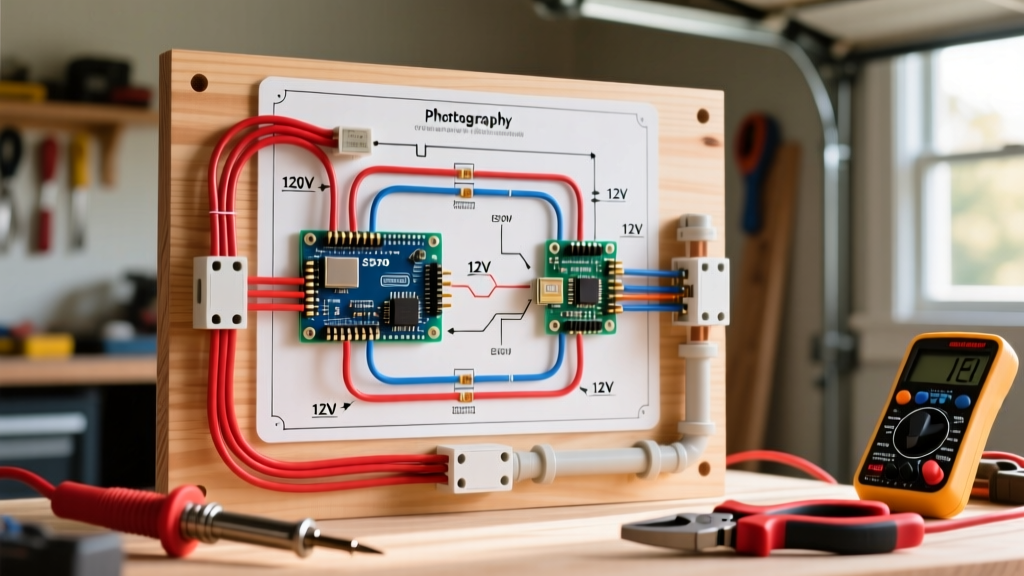

Understanding the RV House vs. Chassis Divide
When engineering or upgrading a Class A, B, or C motorhome, it is critical to understand the duality of the vehicle's electrical architecture. The system is strictly divided into two domains: the chassis system (which handles the engine, starting battery, and headlights) and the house system (which powers the living quarters, appliances, and outlets). A comprehensive house electrical wiring diagram focuses exclusively on the latter, managing the complex interplay between 120V AC shore power, 12V DC battery banks, and high-wattage inverter-chargers.
Unlike stationary residential wiring, an RV house system must endure constant vibration, extreme temperature fluctuations, and mobile power sourcing. According to the Recreational Vehicle Industry Association (RVIA), all motorhome house wiring must comply with strict adaptations of the National Electrical Code (NEC) tailored for mobile environments, mandating specific wire types, strain reliefs, and overcurrent protection methods.
Core Components of the Motorhome House Electrical Wiring Diagram
A modern 2026 RV house electrical wiring diagram relies on a centralized inverter-charger acting as the brain of the operation. Below are the primary nodes you must map out in your schematic:
- Inverter/Charger: The Victron Energy MultiPlus 12/3000/120-50 (Model PMP123021102) is the industry standard for high-end motorhomes. It features an integrated 50A automatic transfer switch (ATS) and a 120A battery charger.
- House Battery Bank: Lithium Iron Phosphate (LiFePO4) is the baseline for 2026. A typical setup utilizes four 12V 100Ah batteries (e.g., Battle Born BB10012) wired in parallel for 400Ah of usable capacity, paired with a smart Battery Management System (BMS).
- 120V AC Distribution Panel: A Square D QO series load center, specifically designed to handle the split-phase or single-phase 120V loads of roof air conditioners and residential refrigerators.
- 12V DC Distribution Panel: Blue Sea Systems C-Series or ST-Series panels, utilizing blade fuses or surface-mount circuit breakers for LED lighting, water pumps, and slide-out motors.
12V DC and 120V AC Wire Sizing Matrix
Voltage drop is the silent killer of RV house systems. Running undersized wire on the 12V DC side will cause your inverter to trigger low-voltage disconnects under heavy load, while undersized 120V AC wire creates severe fire hazards. The National Fire Protection Association (NFPA 70 / NEC) provides strict ampacity tables, but mobile applications require an additional 20% derating for engine compartment heat and bundled wire runs.
| System Voltage | Max Continuous Amps | Recommended AWG (Up to 10ft) | Recommended AWG (10ft - 20ft) | Wire Type Specification |
|---|---|---|---|---|
| 12V DC (Inverter Feed) | 250A - 300A | 2/0 AWG | 4/0 AWG | Marine-grade tinned stranded copper |
| 12V DC (Branch Circuits) | 15A - 20A | 12 AWG | 10 AWG | Marine-grade tinned stranded copper |
| 120V AC (Shore/Inverter) | 30A | 10 AWG | 8 AWG | THHN/THWN stranded in flexible conduit |
| 120V AC (Branch 15A) | 15A | 14 AWG | 12 AWG | THHN/THWN stranded in flexible conduit |
Expert Note: Never use solid-core residential Romex (NM-B) wire in a motorhome house electrical wiring diagram. The constant chassis vibration will cause solid copper to work-harden, snap, and arc inside the walls. Always use stranded wire.
Step-by-Step Wiring Execution Flow
Executing the house electrical wiring diagram requires a specific sequence to ensure safety and proper logic flow through the automatic transfer switches.
Phase 1: High-Current DC Infrastructure
- Battery to Busbar: Run 4/0 AWG marine-grade stranded wire from the positive terminal of the LiFePO4 bank to a Blue Sea Systems 250A busbar. Install a Class T 400A fuse (e.g., Bussmann JJN-400) within 7 inches of the battery positive terminal to protect against catastrophic short circuits.
- Busbar to Inverter: Connect the DC busbar to the Victron MultiPlus DC input terminals. Use a Mega fuse or Class T fuse on the positive line, sized 20% above the inverter's maximum continuous draw (typically a 350A fuse for a 3000W inverter).
- Grounding: Bond the negative busbar directly to the vehicle's main chassis ground point using the same 4/0 AWG wire gauge as the positive feed.
Phase 2: 120V AC Routing and Transfer Logic
- Shore Power Inlet: Wire the 30A or 50A shore power inlet directly to the "AC IN" terminals on the inverter-charger. The Victron MultiPlus contains an internal ATS that will seamlessly pass shore power through to the "AC OUT" terminals when detected.
- AC OUT to Sub-Panel: Route the 120V AC OUT from the inverter to the main Square D QO house distribution panel. This ensures that when the inverter is active, the entire house panel is energized.
- Heavy Load Isolation (Optional): If running multiple roof air conditioners off a 3000W inverter, install an automatic generator start (AGS) relay or a smart load-shedding device (like the Victron Cerbo GX with current limiters) to prevent inverter overload when the microwave and AC compressor kick on simultaneously.
Advanced Troubleshooting: Neutral Bonding & GFCI Nuisance Trips
The most common failure mode in DIY or poorly engineered RV house electrical wiring diagrams involves the Neutral-Ground bond. In a standard brick-and-mortar home, the neutral and ground are bonded at the main service panel. In an RV, this bond must be dynamic.
When plugged into shore power, the neutral-ground bond occurs at the RV park's main pedestal. If your RV's house sub-panel also has a neutral-ground bonding screw installed, you create a parallel neutral path. This will immediately trip the RV park's GFCI breakers and can energize the RV's exterior chassis with lethal voltage.
The Solution: Your house electrical wiring diagram must utilize an inverter-charger with an internal neutral-ground relay (like the Victron MultiPlus or Xantrex Freedom X). When the RV is on shore power, the relay opens, separating neutral and ground inside the RV. When the inverter takes over, the relay closes, creating the necessary bond for GFCI outlets to function correctly inside the motorhome. Always remove the green bonding screw from your RV's internal AC sub-panel.
2026 Bill of Materials & Cost Breakdown
Building a robust, code-compliant motorhome house system requires a significant investment in marine-grade components. Below is a realistic 2026 cost matrix for a premium 3000W inverter setup with 400Ah of lithium storage:
| Component Category | Specific Model / Spec | Est. 2026 Price (USD) |
|---|---|---|
| Inverter/Charger | Victron MultiPlus 12/3000/120-50 | $1,550.00 |
| Battery Bank | 4x Battle Born 100Ah 12V LiFePO4 | $3,396.00 |
| DC Distribution & Fusing | Blue Sea C-Series Panel + Class T Fuses | $450.00 |
| AC Distribution Panel | Square D QO 12-Space Main Lug | $125.00 |
| Wire & Terminals | 4/0 AWG Marine Wire, 10 AWG THHN, Lugs | $600.00 |
| System Monitoring | Victron Cerbo GX + Touch 50 Display | $650.00 |
| Total Estimated Hardware Cost | $6,771.00 | |
For further reading on mobile electrical safety and advanced inverter programming, refer to the Victron Energy Wiring Unlimited Whitepapers, which provide exhaustive diagrams on mobile neutral switching and alternator-charging integration for house banks.