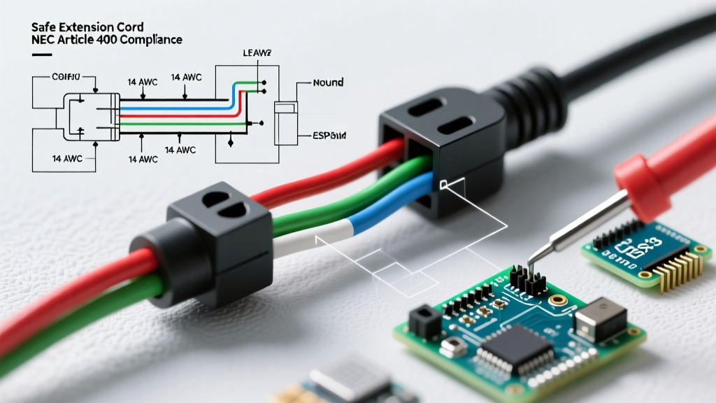

The Critical Intersection of Extension Cord Wiring and NEC Safety Codes
Every year, improper extension cord usage and faulty DIY repairs contribute to thousands of electrical fires and workplace injuries. While purchasing a pre-manufactured, UL-listed cord is always the safest route for temporary power, professionals in construction, event production, and industrial maintenance frequently need to assemble or repair heavy-duty custom lengths. Understanding the correct wiring diagram for extension cord assembly is not just about making a functional connection; it is about strict adherence to the National Electrical Code (NEC) and OSHA workplace safety standards.
According to the National Fire Protection Association (NFPA) 70, flexible cords and cables must be used only as permitted by Article 400. Miswiring a plug, failing to secure the strain relief, or using undersized conductors can lead to catastrophic thermal runaway. This guide provides a comprehensive, code-compliant wiring diagram, voltage drop matrices, and assembly protocols for heavy-duty 120V extension cords.
Anatomy of a Code-Compliant Heavy-Duty Cord
Before consulting the wiring diagram, you must select the correct cable jacket and gauge. Standard household vinyl cords (designations like SVT or SPT) are strictly prohibited for heavy-duty or outdoor commercial use. For professional assembly, you must source SOOW or SJTW cables.
- SOOW (Service, Oil-resistant, Oil-resistant, Weather-resistant): Features a thermoset rubber jacket. It is highly flexible, resistant to abrasion, oils, and extreme temperatures. Ideal for industrial and construction environments. Pricing averages $1.50 to $2.20 per foot for 12/3 AWG.
- SJTW (Sun, Jacket, Thermoplastic, Weather-resistant): Features a PVC thermoplastic jacket. It is lighter and cheaper ($0.80 to $1.20 per foot for 12/3 AWG) but becomes stiff in freezing temperatures and degrades faster under UV exposure compared to SOOW.
The Wiring Diagram: Terminal Mapping and Color Codes
When assembling a standard NEMA 5-15P (15-Amp, 125-Volt) or NEMA 5-20P (20-Amp, 125-Volt) plug, the internal wiring diagram follows a strict color-to-terminal mapping. Reversing the hot and neutral wires creates a severe shock hazard, as the device's internal switch will break the neutral path while leaving the internal components energized.
Standard 3-Prong (Grounding) Connection Matrix
| Conductor Color | Function | Terminal Screw Color | Blade/Pin Type |
|---|---|---|---|
| Black | Hot (Line) | Brass (Gold) | Small / Narrow Blade |
| White | Neutral (Grounded) | Silver | Large / Wide Blade |
| Green | Equipment Ground | Green | Round / U-Shaped Pin |
Expert Insight: Never tin (solder) the stranded wire ends before inserting them under the terminal screws. Solder creeps under the mechanical pressure of the screw over time, leading to a loose connection, increased resistance, and eventual arcing. Always use properly crimped spade or ring terminals, or loop the bare stranded wire clockwise around the screw.
Step-by-Step Assembly and Strain Relief Protocol
Following the wiring diagram is only half the battle. The mechanical assembly dictates the cord's lifespan and safety. According to OSHA Standard 1926.405, flexible cords must be protected from damage, and strain relief must be properly implemented.
- Jacket Stripping: Score the outer jacket carefully using a specialized cable stripper (e.g., the Jonard JIC-4860). Remove exactly 2.5 inches of the outer jacket. Do not nick the inner conductor insulation.
- Conductor Preparation: Strip 0.5 inches of insulation from the black, white, and green conductors. Twist the strands tightly clockwise to prevent fraying.
- Terminal Connection: Form a small hook at the end of each conductor. Loop the hook clockwise around the corresponding terminal screw (Black to Brass, White to Silver, Green to Green). This ensures that tightening the screw pulls the loop closed rather than pushing it out. Torque the screws firmly until the wire is immobilized.
- Strain Relief Clamping: This is the most critical safety step. The internal cord grip (strain relief bar) inside the plug housing must clamp down exclusively on the thick outer jacket of the cable, never on the individual colored conductors. If the grip clamps the inner wires, a sharp tug will pull the wires directly out of the terminal screws, causing a short circuit.
- Insulation Verification: Ensure no bare copper is visible outside the terminal screws. Exposed copper increases the risk of phase-to-ground faults.
Voltage Drop and Wire Gauge Selection Matrix
A common failure mode in DIY extension cords is using 14 AWG wire for long runs, resulting in severe voltage drop. When voltage drops below 110V on a 120V circuit, motors (like those in table saws or air compressors) draw excess amperage to compensate, leading to burned-out windings and tripped breakers. The Electrical Safety Foundation International (ESFI) strongly advises against undersizing cords for high-draw equipment.
| Wire Gauge (AWG) | Max Amperage | Voltage Drop at 50 ft (15A Load) | Voltage Drop at 100 ft (15A Load) | Recommended Use Case |
|---|---|---|---|---|
| 14 AWG | 15 Amps | 1.55V (1.3%) | 3.10V (2.6%) | Light indoor duty, short runs (<25 ft) |
| 12 AWG | 15-20 Amps | 0.98V (0.8%) | 1.95V (1.6%) | Standard job site, power tools, 50-100 ft runs |
| 10 AWG | 20-30 Amps | 0.61V (0.5%) | 1.23V (1.0%) | Heavy machinery, RV hookups, runs >100 ft |
NEC Article 400.8: Prohibited Uses and Code Violations
Even if your wiring diagram and assembly are flawless, using the extension cord in a manner prohibited by the NEC renders the installation illegal and highly dangerous. NEC Article 400.8 explicitly outlines 'Uses Not Permitted' for flexible cords. Inspectors will fail any site where these rules are violated.
Where You CANNOT Use an Extension Cord
- Concealed Wiring: Cords cannot be run through holes in walls, structural ceilings, suspended ceilings, dropped ceilings, or floors.
- Permanent Infrastructure: They cannot be attached to building surfaces or concealed behind drywall, baseboards, or cabinetry.
- Environmental Hazards: Standard cords cannot be run through doorways, windows, or similar openings where they can be pinched or crushed, unless specifically protected by a heavy-duty conduit or ramp.
- Daisy Chaining: Plugging one extension cord into another (daisy-chaining) violates OSHA regulations and NEC guidelines, as the cumulative resistance increases the fire risk and defeats the overcurrent protection of the branch circuit breaker.
Recommended Heavy-Duty Components for 2026 Assembly
To build a cord that survives commercial abuse, avoid big-box store generic plugs. Invest in industrial-grade NEMA connectors. Here are the current industry-standard components for professional assembly:
- Hubbell 5266 (15A, 125V Industrial Plug): Priced around $14.50. Features a ribbed thermoplastic elastomer housing that provides superior impact resistance and a double-wall cord grip for unmatched strain relief.
- Leviton 5266-C (15A, 125V Pro Grade Plug): Priced around $11.00. Features brass terminal screws with deep slotted heads for high-torque tightening and a clear polycarbonate terminal body that allows visual inspection of the wire seating.
- Southwire 12/3 SOOW Portable Power Cable: Priced at approximately $1.60 per foot. Features 600V rated insulation and a robust CPE (Chlorinated Polyethylene) jacket that resists chemical spills and physical abrasion.
Catastrophic Failure Modes in DIY Cord Assembly
When the wiring diagram is misinterpreted or assembly steps are rushed, specific failure modes emerge in the field. Understanding these edge cases separates amateur DIYers from seasoned electrical professionals.
1. The 'Neutral-to-Ground' Bond Error
A fatal error occurs when a DIYer accidentally bridges the neutral (silver) and ground (green) terminals inside the plug. In a properly wired system, the neutral carries the return current, while the ground carries zero current unless a fault occurs. Bonding them at the extension cord plug creates a parallel path for return current to flow through the equipment grounding conductor. This can energize the metal chassis of connected tools, presenting a lethal shock hazard if the ground pin is ever compromised.
2. Thermal Runaway from Loose Terminals
If the terminal screw is not tightened to the proper torque, the contact area between the wire and the brass screw is reduced. This micro-gap increases electrical resistance. As current flows (e.g., a 14A draw from a miter saw), the high-resistance joint generates intense heat (following Joule's First Law, $P = I^2R$). This heat melts the surrounding PVC or thermoplastic housing, eventually causing a phase-to-ground arc flash inside the plug.
3. Jacket Creep and Conductor Exposure
If the strain relief bar is clamped over the inner conductors instead of the outer jacket, the repetitive pulling of the cord will cause the outer jacket to slide backward ('jacket creep'). This exposes the inner colored wires to UV light, physical abrasion, and moisture, rapidly degrading the insulation and leading to short circuits.
Final Safety Verification
After assembling your extension cord using the correct wiring diagram and heavy-duty components, always verify the assembly before putting it into service. Use a commercial-grade receptacle tester (such as the Klein Tools RT250 or Gardner Bender GRT-300) to check for correct wiring, open grounds, and reversed polarity. Furthermore, perform a physical tug-test on the cord grip to ensure the strain relief is holding the outer jacket securely. By respecting the NEC codes and utilizing precise assembly techniques, you ensure that your temporary power solutions remain safe, legal, and highly reliable on any job site.