
Understanding the Two Way Switch: Terminology and Global Standards
When searching for a wiring diagram for two way switch configurations, the first hurdle for DIYers and even seasoned electricians is navigating regional terminology. In the UK, Australia, and regions following IEC standards, a '2-way switch' refers to a setup that allows you to control a single lighting load from two different locations (e.g., the top and bottom of a staircase). However, in the United States and Canada, governed by the National Electrical Code (NEC), this exact same dual-location functionality is achieved using what is officially termed a 3-way switch. Conversely, a standard US single-pole switch (which controls a light from one location) only has two terminal screws, leading some international readers to mistakenly call it a '2-way'.
For the purpose of this safety and code compliance guide, we will focus on the dual-location control circuit (US 3-way / IEC 2-way). Misunderstanding this nomenclature is a leading cause of improper wiring, short circuits, and severe shock hazards. According to the National Fire Protection Association (NFPA), improper switch wiring and overfilled junction boxes remain primary catalysts for residential electrical fires.
Global Nomenclature Comparison Matrix
| Feature | US / Canada (NEC) | UK / Australia (IEC) | Terminals on Switch |
|---|---|---|---|
| Single Location Control | Single-Pole Switch | 1-Way Switch | 2 (Line, Load) |
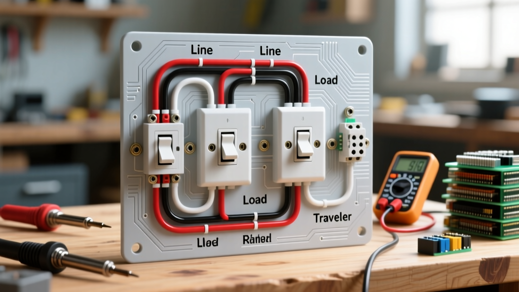
| Dual Location Control | 3-Way Switch | 2-Way Switch | 3 (Common, 2 Travelers) |
| Three+ Location Control | 4-Way Switch | Intermediate Switch | 4 (In/Out Travelers) |
Critical NEC Code Requirements for Dual-Location Switches
Wiring a dual-location switch is not merely about making the light turn on; it is about ensuring the circuit meets modern safety benchmarks. The NEC has undergone significant revisions in recent cycles (carrying through to the 2026 enforcement standards) that fundamentally change how these switches must be wired.
1. The Neutral Wire Mandate (NEC 404.2(C))
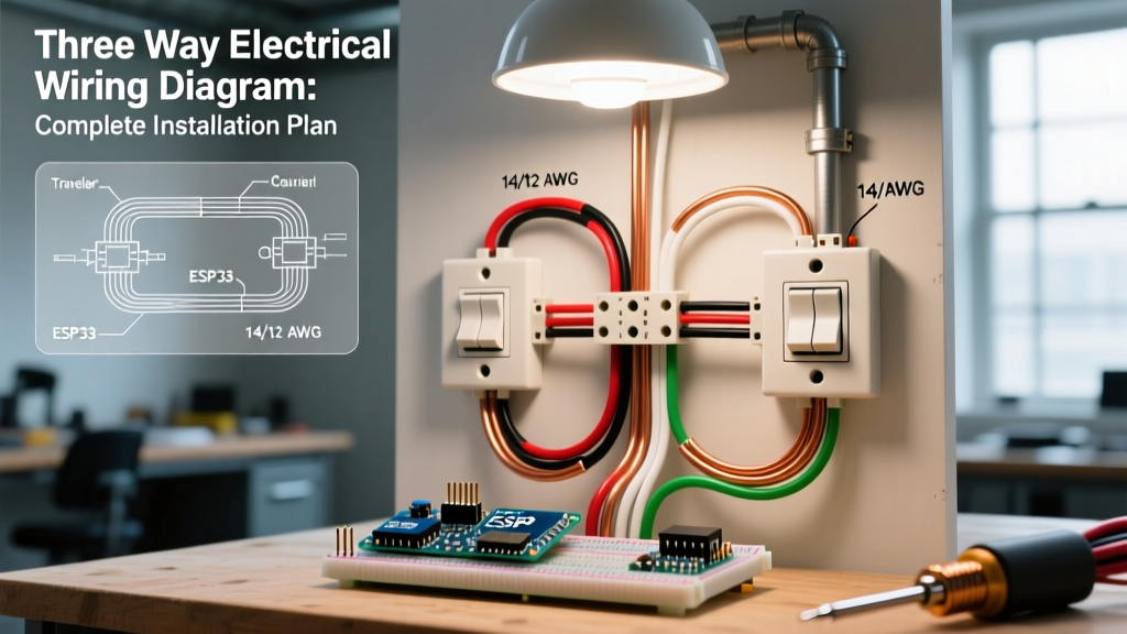
Historically, electricians used the white wire in a 14/3 or 12/3 NM-B (Romex) cable as a 'traveler' between two 3-way switches, re-identifying it with black tape. This is no longer code-compliant in new installations. NEC Article 404.2(C) mandates that a grounded circuit conductor (neutral) must be provided at the switch location. This was introduced to support smart switches, occupancy sensors, and LED drivers that require a neutral to function without leaking current through the ground wire. If your wiring diagram for two way switch setups does not include a continuous neutral passing through both switch boxes, it will fail inspection.
2. Box Fill Calculations (NEC 314.16)
Dual-location switches require more wires entering the box than standard switches. Overcrowding causes wire insulation damage and heat buildup. You must calculate box fill based on the wire gauge:
- 14 AWG Wire: 2.0 cubic inches per conductor.
- 12 AWG Wire: 2.25 cubic inches per conductor.
Calculation Example (14 AWG 3-Way Switch Box):
3 current-carrying conductors entering/leaving (6.0 cu in) + 1 internal clamp (2.0 cu in) + 1 device yoke (4.0 cu in) + 1 equipment grounding conductor (2.0 cu in) = 14.0 cubic inches minimum. A standard 'single-gang old work' box is often only 14 to 16 cubic inches, leaving zero margin for error. Always opt for deep 22+ cubic inch boxes for dual-location switch endpoints.
3. Equipment Grounding (NEC 250.148)
According to OSHA Electrical Standards and NEC 250, all switch boxes must have an effective ground-fault current path. If you are using metal switch boxes, the bare copper ground wire must be pigtailed: one branch to the metal box's grounding screw, and one branch to the green grounding screw on the switch itself. Never daisy-chain the ground wire through the switch yoke.
Step-by-Step Wiring Scenarios: Power Source Location
The physical routing of your cables dictates which wiring diagram for two way switch setups you must follow. There are two primary scenarios.
Scenario A: Power Source at the First Switch
- Panel to Switch 1: Run 14/2 NM-B (15A circuit) or 12/2 NM-B (20A circuit). The black wire is the Line (Hot), the white is the Neutral.
- Switch 1 to Switch 2: Run 14/3 NM-B. The white wire is spliced directly to the incoming neutral (satisfying NEC 404.2(C)). The black and red wires connect to the brass 'traveler' screws on Switch 1.
- Switch 2 to the Light Fixture: Run 14/2 NM-B. The white wire connects to the neutral bundle. The black wire connects to the black 'traveler' wire from the 14/3 cable using a wire nut, acting as the switched hot to the fixture.
- Common Terminals: The black (hot) from the panel connects to the dark 'common' screw on Switch 1. The black (switched hot) going to the light connects to the dark 'common' screw on Switch 2.
Scenario B: Power Source at the Light Fixture
This is common in retrofit situations but requires careful neutral management.
- Panel to Light: 14/2 NM-B provides constant hot and neutral to the ceiling box.
- Light to Switch 1: Run 14/3 NM-B. The white wire serves as the neutral down to the switch box. The black wire serves as the constant hot from the ceiling. The red wire acts as the 'switched hot' returning to the light.
- Switch 1 to Switch 2: Run another 14/3 NM-B. White is neutral (spliced through). Black and Red are travelers.
If you are forced by existing structural constraints to use a white wire as a 'switched hot' or 'traveler' in an older retrofit (grandfathered under older NEC cycles), NEC 200.7(C) strictly requires you to permanently re-identify the white insulation with black or red electrical tape or paint at every point the wire is accessible. However, for all 2026 new construction and major renovations, a dedicated neutral must be present, eliminating the need to repurpose the white wire.
Recommended Components for Code-Compliant Installations
Using contractor-grade or residential-grade hardware ensures the terminal screws can handle the torque requirements without stripping, and the internal contacts resist arcing. The Electrical Safety Foundation International (ESFI) warns against using uncertified, ultra-cheap components found on third-party marketplaces, as they often lack UL/CSA listing and internal arc shields.
- Leviton Decora 5603-2W (15A 3-Way Switch): Priced around $4.50 - $6.00. Features a shallow profile for easier box fill management and a green grounding screw positioned for easy access.
- Lutron Claro C-3PS-WH (15A 3-Way Switch): Priced around $7.00 - $9.00. Excellent for tight spaces; the rocker design prevents dust accumulation in the toggle gap.
- Wago 221 Series Lever Nuts: Priced at $0.40 - $0.60 each. While traditional wire nuts are code-compliant, Wago lever nuts provide a verifiable, visual connection that drastically reduces the risk of loose traveler wires causing intermittent arcing.
Common Failure Modes and Troubleshooting
When a dual-location circuit fails, it is rarely a bad switch; it is almost always a wiring topology error. Here are the most common failure modes:
1. The 'Traveler-to-Common' Swap
Symptom: Switch 1 turns the light on, but Switch 2 only works if Switch 1 is in the 'ON' position. If Switch 1 is 'OFF', Switch 2 does nothing.
Cause: The constant hot wire was mistakenly connected to a brass traveler screw instead of the black common screw on Switch 1.
Fix: Verify the wire carrying constant 120V (tested with a non-contact voltage tester or multimeter) is exclusively on the dark-colored common screw.
2. Bootleg Grounds and Shared Neutrals
Symptom: GFCI or AFCI breakers trip immediately when the switch is toggled.
Cause: The neutral returning from the light fixture is passing through the switch box but is inadvertently touching the ground wire, or the neutral is shared with a completely different circuit (a massive NEC violation).
Fix: Isolate the neutral bundle. Ensure neutrals only mate with neutrals from the same exact breaker circuit.
3. Smart Switch Incompatibility
Symptom: Installing a smart 3-way switch (like the Kasa KS230) results in the switch rebooting constantly or failing to connect to Wi-Fi.
Cause: The smart switch requires a dedicated neutral to power its internal radio, but the installer used an old wiring diagram that repurposed the white wire as a traveler.
Fix: You must pull a new 14/3 or 14/4 cable to provide a true neutral to the smart switch master unit, or switch to a system that uses a wireless remote (like the Lutron Caseta Pico) which bypasses the neutral requirement at the secondary location.
Frequently Asked Questions (FAQ)
Can I use a 14/2 cable between the two switches?
No. A 14/2 cable only provides a black, white, and bare ground. To meet NEC 404.2(C) neutral requirements while also providing two traveler wires, you absolutely must use a 14/3 cable (Black, Red, White, Bare) between the switch locations.
Do the traveler wires need to be specific colors?
The NEC does not mandate specific colors for traveler wires, only that they are not white, gray, or green (which are reserved for neutral and ground). However, industry best practice is to use the red and black wires in a 14/3 cable as travelers to maintain consistency and aid future troubleshooting.
What happens if I mix 14 AWG and 12 AWG wire in a 3-way circuit?
While physically possible, it is a severe code violation and safety hazard if the circuit is protected by a 20A breaker. If any part of the circuit uses 14 AWG wire (rated for 15A), the entire circuit must be protected by a 15A breaker. Mixing gauges can lead to the 14 AWG wire melting inside the wall before the 20A breaker trips.