
Introduction to Schematic Literacy
Understanding how to read electrical wiring diagram documentation is the dividing line between a successful DIY installation and a catastrophic failure. Whether you are troubleshooting a 240V HVAC compressor, wiring a new subpanel, or integrating a microcontroller relay bank, the schematic is your definitive roadmap. In 2026, with the widespread adoption of the latest National Electrical Code (NEC) updates and smart-home integrations, diagrams have become more complex, blending high-voltage power circuits with low-voltage digital control logic. This step-by-step walkthrough will teach you to decode industry-standard schematics, trace power flow, and verify your work in the field with absolute precision.
Phase 1: Identify the Diagram Standard (NEMA vs. IEC)
Before tracing a single wire, you must identify the graphical language the diagram uses. The two dominant global standards are NEMA and IEC.
NEMA Ladder Logic (North America)
Developed by the National Electrical Manufacturers Association, NEMA diagrams dominate US residential, commercial, and industrial panels. They utilize "ladder logic," where two vertical lines (the "rails") represent the power source, and horizontal lines (the "rungs") represent individual control or power circuits. This format reads from left to right, top to bottom, mimicking the physical layout of a standard North American breaker panel.
IEC Block Diagrams (International & Modern Appliances)
The International Electrotechnical Commission (IEC) standard is prevalent in European equipment, imported appliances, and modern variable frequency drives (VFDs). Instead of ladder logic, IEC uses functional block diagrams. Components are grouped by their logical function rather than their physical wiring sequence. If you are wiring an imported mini-split HVAC system or a European-manufactured motor controller, expect IEC symbols, which use distinct alphanumeric designators (e.g., K1 for contactors, F1 for fuses) rather than NEMA's graphical representations.
Phase 2: Map the Power Rails and Circuit Boundaries
Once the standard is identified, locate the power source. In a NEMA ladder diagram, the left vertical rail is typically L1 (Line 1 / Hot), and the right rail is L2 (Line 2 / Neutral or the second Hot leg in a 240V system).
- Single-Phase 120V Circuits: L1 is the ungrounded conductor (black wire), and L2 is the grounded neutral (white wire). Every rung must connect L1 to L2 to complete the circuit.
- Single-Phase 240V Circuits: L1 and L2 are both ungrounded hot legs (typically black and red). There is no neutral on the rails unless a specific 120V control tap is drawn.
- Three-Phase Industrial: You will see L1, L2, and L3. Always trace the phase rotation indicators on the diagram to ensure correct motor spin direction before energizing.
Pro Tip: Always look for the main disconnect switch or primary fuse block at the very top of the diagram. This is your Lockout/Tagout (LOTO) point. According to OSHA electrical safety guidelines, you must verify zero energy at this exact point before touching any downstream terminals.
Phase 3: Decode Control Logic and Interlocks
The most common mistake DIYers make when learning how to read electrical wiring diagram layouts is confusing the power circuit with the control circuit. In motor starters and HVAC systems, these are physically and logically separated.
Normally Open (NO) vs. Normally Closed (NC)
Control logic relies on switches, relays, and contactors. You must understand their "normal" state—the state they rest in when no power or physical force is applied.
- Normally Open (NO): Represented by two parallel lines with a gap. The circuit is broken until the relay coil energizes or a button is pressed. Example: A start button on a motor controller.
- Normally Closed (NC): Represented by two parallel lines crossed by a diagonal slash. The circuit flows until the relay energizes or a safety limit is tripped. Example: A thermal overload relay or an emergency stop button.
Electrical Interlocks
Look for dashed lines connecting switch contacts to relay coils. This indicates a mechanical or electrical interlock. For instance, in a reversing motor starter (like a Square D TeSys D-line), an electrical interlock ensures the "Forward" and "Reverse" contactors cannot close simultaneously, which would cause a catastrophic phase-to-phase short circuit.
Phase 4: Cross-Reference Wire Gauges and NEC Insulation Codes
A schematic tells you where wires go, but the accompanying wire schedule or notes section tells you what wires to use. Modern diagrams will specify wire gauge (AWG) and insulation type. Misinterpreting this can lead to melted insulation and electrical fires.
Per the National Fire Protection Association (NFPA 70 / NEC), specifically Article 310, you must match the insulation type to the environment. Here is a breakdown of the most common wire types specified in 2026 wiring diagrams:
| Insulation Type | Max Temp Rating | Primary Use Case & Environment |
|---|---|---|
| THHN | 90°C (Dry Only) | Standard indoor residential conduit, dry panels. Not rated for wet outdoor locations. |
| THWN-2 | 90°C (Wet or Dry) | Outdoor conduit, underground wet vaults, HVAC exterior disconnects. The modern dual-rated standard. |
| XHHW-2 | 90°C (Wet or Dry) | High-density commercial panels, tighter conduit bend radiuses. Cross-linked polyethylene (XLPE) jacket. |
The 60°C Termination Rule (NEC 110.14(C))
Even if your diagram specifies 12 AWG THHN wire (rated for 30 Amps at 90°C in the conduit), NEC Article 110.14(C) dictates that for circuits rated 100A or less, you must size the wire based on the 60°C column of the ampacity table unless the equipment lugs are explicitly marked otherwise. Therefore, that 12 AWG wire is legally limited to 20 Amps at the breaker. Always check the terminal block specifications on the diagram for the "Cu 75°C" or "Cu 60°C" marking.
Phase 5: Field Verification and Ghost Voltage Elimination
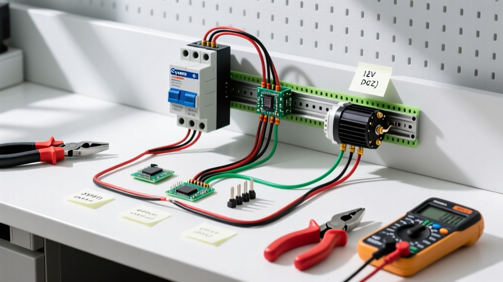
Reading the diagram is only half the battle; verifying the physical installation against the diagram is where true expertise lies. When tracing circuits in the field, rely on a True-RMS digital multimeter (DMM) like the Fluke 87V or Fluke 117.
Step-by-Step Verification Protocol
- Continuity Testing (De-energized): With the main breaker OFF and LOTO applied, use the DMM's continuity beep function. Touch one probe to L1 at the breaker and the other to the input side of the contactor. A beep confirms the physical wire matches the schematic rung.
- Voltage Drop Testing (Energized): Under load, measure the voltage across the breaker, then across the contactor terminals. A drop greater than 3% (e.g., dropping from 240V to 232V) indicates a loose termination or an undersized wire run not accounted for in the original diagram.
- Eliminating Ghost Voltages: When troubleshooting open control circuits, high-impedance multimeters can read "ghost voltages" (induced voltage from adjacent live wires in the same conduit) showing 40V-60V on a dead wire. Switch your Fluke DMM to LoZ (Low Impedance) mode. LoZ bleeds off capacitive coupling, dropping the ghost voltage to 0.0V and confirming the circuit is truly open.
Safety Warning: Never assume a diagram reflects the physical reality of an older panel. Previous owners or unlicensed handymen frequently bypass interlocks or swap wire colors. Always treat every conductor as live until tested. Adhere strictly to OSHA Subpart S electrical safety standards regarding PPE and approach boundaries when working inside energized panels.
Conclusion
Mastering how to read electrical wiring diagram documentation requires a systematic approach: identify the standard, map the power rails, decode the control logic, respect NEC insulation and ampacity rules, and rigorously verify in the field. By treating the schematic as a legally binding contract rather than a rough suggestion, you ensure your electrical projects are not only functional but fundamentally safe and code-compliant for years to come.