
Understanding the Wiring Diagram for Nest Thermostats
Upgrading to a smart thermostat is one of the most effective ways to improve home energy efficiency, but interfacing modern electronics with legacy HVAC control boards introduces distinct electrical hazards. When consulting a wiring diagram for Nest thermostats (including the Nest Learning Thermostat 4th Gen and the standard Nest Thermostat), the primary concern is not just functionality—it is strict adherence to low-voltage safety codes and the prevention of catastrophic equipment failure. A single miswired terminal can instantly destroy the thermostat's internal triacs, blow the air handler's control board fuse, or worse, introduce line voltage into a Class 2 circuit, creating a severe fire hazard.
This comprehensive guide breaks down the official wiring diagram for Nest devices through the lens of the National Electrical Code (NEC), focusing on safe termination practices, C-wire compliance, and edge-case troubleshooting for complex HVAC systems.
NEC Code Compliance & Low-Voltage Safety Standards
Thermostat wiring falls under NFPA 70 (National Electrical Code) Article 725, which governs Class 1, Class 2, and Class 3 remote-control, signaling, and power-limited circuits. Standard residential HVAC control circuits operate at 24VAC (nominal) and are classified as Class 2 power-limited circuits.
CRITICAL SAFETY WARNING: Never connect 120V or 240V line-voltage wires to a Nest thermostat baseplate. Older homes with electric baseboard heaters or certain wall heaters may use line-voltage thermostats. The Nest is strictly designed for 24VAC systems. Connecting line voltage will cause an immediate explosive failure of the device and pose a lethal shock and fire risk. Always verify voltage with a CAT III multimeter before proceeding.
Furthermore, all smart thermostats must comply with UL 60730, the standard for automatic electrical controls. This standard dictates how the device must handle power anomalies, relay switching, and thermal limits. Bypassing safety protocols—such as using undersized wire or improper splicing—voids the UL listing and violates NEC Article 110.3(B), which requires equipment to be installed in accordance with its listing and labeling instructions.
Terminal Mapping and Voltage Tolerances
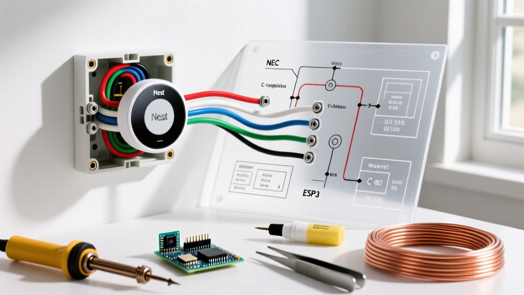
The Google Nest Official Wiring Guide provides a baseline for terminal assignments, but understanding the electrical tolerances and failure modes of each terminal is crucial for professional-grade installations. Below is the technical mapping for standard Nest terminals.
| Terminal | Function | Nominal Voltage | Common Failure Mode if Miswired |
|---|---|---|---|
| Rh / Rc | 24VAC Power (Heating / Cooling) | 24VAC (16V-30V) | Shorts to C or G; blows 3A ATC fuse on HVAC board. |
| W1 / W2 | First / Second Stage Heat Relay | 24VAC (Switched) | Continuous heating; triac short if wired to high voltage. |
| Y1 / Y2 | First / Second Stage Cooling Relay | 24VAC (Switched) | Compressor short-cycling; contactor coil burnout. |
| G | Indoor Blower Fan Relay | 24VAC (Switched) | Fan runs continuously; limits cooling efficiency. |
| O/B | Heat Pump Reversing Valve | 24VAC (Switched) | Heat pump blows cold air in winter (O vs B logic error). |
| C | Common Wire (24VAC Return) | 0V Reference | Power stealing causes phantom relay clicking and H04 errors. |
The C-Wire Controversy: Code, Safety, and Power Stealing
The most debated aspect of any wiring diagram for Nest thermostats is the Common (C) wire. The C-wire provides a continuous 24VAC return path to complete the circuit, supplying steady power to the thermostat's Wi-Fi radios, display, and sensors.
How Power Stealing Works (And Why It's Problematic)
If a C-wire is absent, the Nest attempts to 'steal' power by briefly pulsing the heating or cooling relays (e.g., Y1 or W1) during the off-cycle. This draws a small current through the HVAC contactor coil without engaging it. While ingenious, power stealing violates the spirit of UL 60730 reliability standards and causes several real-world issues:
- Phantom Clicking: The HVAC contactor may audibly click or chatter, prematurely wearing out the mechanical relay.
- Short Cycling: On highly sensitive modern gas valves, the micro-current can trick the valve into opening briefly, causing dangerous short-cycling.
- H04 Error Codes: During extreme weather, when the HVAC runs continuously, the Nest cannot pulse the relay to steal power, leading to a drained internal lithium-ion battery and an H04 (no power) shutdown.
Code-Compliant C-Wire Solutions
According to the U.S. Department of Energy, ensuring proper power delivery to smart thermostats is vital for maintaining optimal HVAC efficiency. To resolve a missing C-wire safely and up to code:
- Run New 18/5 Wire: The gold standard. Pulling new 18 AWG solid copper thermostat wire from the air handler to the thermostat wall plate ensures a dedicated, code-compliant Class 2 circuit.
- Install the Nest Power Connector (GAE-0015): Priced around $35, this device wires directly into the air handler's control board in parallel with the existing Rh and W1/Y1 terminals. It synthesizes a clean C-wire signal that travels back to the thermostat via the unused wires in your existing wall bundle, eliminating the need to fish new cables through drywall.
Step-by-Step Safe Installation Protocol
Follow this strict Lockout/Tagout (LOTO) and termination procedure to ensure safety and prevent equipment damage.
1. System De-energization and Verification
Turn off the dedicated breakers for both the indoor air handler/furnace and the outdoor condenser/heat pump. Remove the old thermostat and use a CAT III multimeter set to AC Voltage. Place one probe on the R terminal and the other on the C terminal. The reading must be exactly 0.0V. If you read 24VAC, you have turned off the wrong breaker or the system utilizes a secondary transformer.
2. Wire Preparation and Stripping
Use only 18 AWG solid copper wire. Stranded wire is not permitted for Nest terminal blocks as it frays and causes poor contact or shorts. Strip exactly 1/4 inch (6mm) of insulation. Exposing more than 1/4 inch creates a shock hazard and increases the risk of adjacent wires touching and shorting out the 3A automotive blade fuse located on the HVAC control board.
3. Baseplate Termination
Insert the wire into the Nest baseplate terminal. Tighten the screw until it is finger-tight, then add a quarter-turn with a small Phillips screwdriver. Do not overtighten. The Nest baseplate uses threaded brass inserts encased in plastic; excessive torque will strip the plastic housing, ruining the $130-$280 baseplate.
Edge Cases: Millivolt Systems and Dual Transformers
Millivolt Gas Fireplaces
Standard Nest thermostats require a minimum of 12VAC to boot and operate. Millivolt gas fireplaces generate only ~0.7V via a thermopile, which is insufficient. To control a millivolt fireplace with a Nest, you must install an external 24VAC transformer (plugged into a standard 120V receptacle) and use a 24VAC-rated isolation relay. The Nest switches the relay coil, and the relay's dry contacts switch the millivolt fireplace circuit. Never connect the 24VAC transformer directly to the millivolt gas valve; it will destroy the valve and create a severe gas leak hazard.
Dual Transformer Systems (Rh and Rc)
Some older homes have separate transformers for heating (Rh) and cooling (Rc). The Nest baseplate features an internal jumper connecting Rh and Rc. If your system genuinely uses two independent transformers, the Nest will automatically detect the dual power sources and digitally isolate them. However, if the system uses a single transformer but the previous installer mistakenly separated the wires, the Nest may experience phase-shift issues. Always verify transformer topology at the control board before finalizing the wiring diagram for Nest configurations.
Summary of Best Practices
Adhering to NEC Article 725, utilizing proper 18 AWG solid wire, and ensuring a dedicated C-wire or Nest Power Connector are the hallmarks of a professional, safe installation. By respecting the voltage tolerances and understanding the internal logic of the Nest's power management system, you protect both your expensive HVAC equipment and your home's electrical integrity.