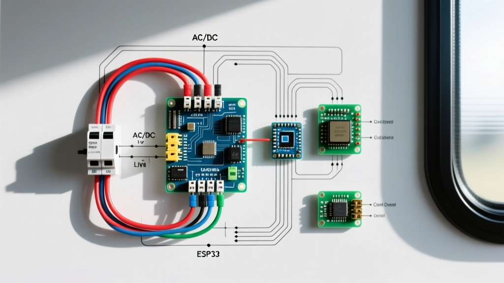

The Anatomy of a Camper Electrical Wiring Diagram
Designing or upgrading a camper electrical wiring diagram requires a fundamental understanding of split-load distribution. Unlike residential homes that rely solely on a 120V/240V AC grid, recreational vehicles and off-grid campers must manage a dual-voltage ecosystem. The distribution panel acts as the central nervous system, bridging shore power, solar charge controllers, lithium battery banks, and AC/DC appliances. In 2026, with the mass adoption of 48V DC architectures and high-wattage induction cooktops, the traditional RV load center has evolved significantly.
A robust camper electrical wiring diagram divides the system into two distinct domains: the AC Load Center (handling 120V shore power and inverter output) and the DC Fuse Block (managing 12V, 24V, or 48V battery distribution). Mismanaging the overcurrent protection devices (OCPDs) in either domain is the leading cause of electrical fires in DIY camper builds. This guide dissects the panel and breaker requirements necessary to keep your rig safe, compliant, and fully powered.
AC Load Center: Breaker Sizing and 120V Routing
The AC distribution panel in a camper typically handles 30-amp or 50-amp shore power inputs. When mapping your camper electrical wiring diagram, you must adhere to the National Electrical Code (NEC) continuous load rules, which dictate that a breaker should only be loaded to 80% of its rated capacity for continuous draws (loads lasting three hours or more).
Calculating AC Breaker Sizes for Camper Appliances
- Air Conditioner (15,000 BTU): Draws roughly 12 to 14 amps at startup and running. Requires a dedicated 20A breaker with 12 AWG THHN wire. Never share this circuit.
- Microwave (900W - 1200W): Draws 8 to 10 amps. A 15A breaker with 14 AWG wire is sufficient, but upgrading to a 20A breaker with 12 AWG wire mitigates voltage drop over long wire runs from the panel to the galley.
- Water Heater (Electric Element): Typically 1440W (12 amps). Requires a dedicated 15A breaker. Because it is a continuous load, a 20A breaker is technically required by strict NEC interpretation, though 15A is common in factory RV builds.
- General Receptacles: Grouped on a 15A or 20A breaker using 14 AWG or 12 AWG wire, respectively. GFCI protection is mandatory for any outlet within 6 feet of a water source (galley sink, bathroom).
DC Distribution: Fuse Blocks and the Low-Voltage Bus
While AC panels use thermal-magnetic circuit breakers, the DC side of your camper electrical wiring diagram relies on blade fuses, ANL fuses, or Class-T fuses. DC arcs are significantly more dangerous than AC arcs because the current does not cross zero 60 times a second to extinguish the spark. Therefore, DC overcurrent protection must be meticulously sized.
Main Feed vs. Branch Circuit Protection
Your main battery positive feed must be protected by a high-amperage Class-T or ANL fuse placed within 7 inches of the battery terminal. This is a strict requirement outlined by the ABYC E-11 standard for DC systems, which is widely adopted as best practice for high-end camper builds. For a 400Ah lithium battery bank pushing 3000W through a 12V inverter, the main feed will see up to 250 amps; a 300A Class-T fuse is mandatory.
Branch circuits are routed through a centralized DC fuse block, such as the Blue Sea Systems ST Blade. Use ATO/ATC blade fuses for standard 12V loads:
- LED Lighting: 5A fuse (18 AWG or 16 AWG wire)
- Water Pump: 10A fuse (14 AWG wire)
- 12V Compressor Fridge: 15A fuse (12 AWG wire to handle startup surge)
- MaxxAir Fan: 5A fuse (16 AWG wire)
2026 Benchmark Camper Panels & Breaker Kits
Selecting the right integrated panel saves hours of fabrication. Below is a comparison of the top-rated AC/DC distribution panels for camper wiring diagrams in 2026.
| Model | AC Breaker Spaces | DC Fuse Circuits | Integrated Converter | Avg. Price (2026) |
|---|---|---|---|---|
| Progressive Dynamics PD4560K18LV8 | 6 Spaces (Tandem capable) | 12 ATC/ATO Fuses | 60A Lithium-Ready | $240 - $270 |
| WFCO WF-8955-PEC | 5 Spaces | 12 ATC/ATO Fuses | 55A (Lead-Acid focused) | $160 - $190 |
| Blue Sea 5025 ST Blade (DC Only) | N/A (DC Only) | 6 Circuits (Negative Bus) | N/A | $45 - $60 |
| Victron Lynx Distributor (High-End) | N/A (DC Mega Fuses) | 4 Mega Fuses (Up to 1000A) | N/A | $310 - $340 |
Note: For modern DIY camper builds utilizing LiFePO4 batteries, ensure your integrated converter features a dedicated lithium charging profile. The PD4560K18LV8 is currently the industry standard for this application.
Calculating Wire Gauge and Voltage Drop
A common failure in camper electrical wiring diagrams is sizing wire solely based on ampacity while ignoring voltage drop. In a 12V DC system, a 3% voltage drop is the maximum allowable threshold for critical electronics. If you are running a 12V compressor fridge that draws 6 amps, and the round-trip wire distance from the DC panel to the fridge is 30 feet, using 14 AWG wire will result in a 4.1% drop. You must step up to 10 AWG wire to keep the drop under 2%, ensuring the fridge's low-voltage cutoff doesn't trigger prematurely.
For precise calculations, professional builders rely on the Blue Sea Systems Circuit Calculator, which factors in wire insulation temperature ratings and specific bundle derating factors.
Common Wiring Diagram Failure Modes & Troubleshooting
Even with a perfect schematic, physical installation errors can compromise the system. Watch out for these specific failure modes:
1. The Inverter Neutral-to-Ground Bonding Error
When wiring an inverter/charger into your AC panel, the inverter must create a neutral-to-ground bond when operating in battery mode, but must isolate that bond when connected to shore power. If your camper electrical wiring diagram hardwires a neutral-to-ground bond at the sub-panel, plugging into shore power will create a parallel neutral path, tripping GFCI breakers and potentially energizing the camper's chassis. Always use an inverter with an internal automatic transfer switch and relay-driven bonding.
2. Multi-Wire Branch Circuit (MWBC) Shared Neutrals
To save space in small AC panels, some builders use a shared neutral for two 120V hot legs. In a residential split-phase 240V system, the neutral only carries the imbalance. However, campers are fed by a single 120V leg from the pedestal. If you put two 15A breakers on the same 120V phase and share a 14 AWG neutral, the neutral will carry the combined 30A load, melt the insulation, and cause a fire. Never use shared neutrals in RV AC panels.
3. DC Fuse Block Negative Bus Bottlenecks
Many entry-level DC fuse blocks feature a small negative busbar on the side rated for only 100A total. If you connect high-draw items like a 12V heated floor system or an electric awning, the negative busbar will overheat. Always route heavy DC negatives directly to a dedicated, high-amperage shunt or main negative busbar, bypassing the fuse block's integrated negative strip.
NFPA 1192 and ABYC Compliance Standards
To ensure your camper electrical wiring diagram meets safety and insurance requirements, it must align with established regulatory frameworks. The NFPA 1192 Standard on Recreational Vehicles governs the AC wiring methods, requiring stranded copper wire (never solid core residential Romex, which fractures under vehicular vibration) and specific Romex connector clamps to prevent chassis chafing.
For the DC side, while ABYC (American Boat &Yacht Council) standards are technically for marine vessels, the Progressive Dynamics and Victron Energy engineering teams universally recommend ABYC E-11 compliance for RV DC systems due to its rigorous vibration, moisture, and overcurrent testing protocols. Using marine-grade tinned copper wire (like Ancor or GS Power) and adhesive-lined heat shrink for all DC terminations is the hallmark of a professional-grade camper build.
Pro-Tip for 2026 Builds: Always install a 500A/50mV DC shunt on the main negative battery feed and wire it to a Bluetooth battery monitor (like the Victron SmartShunt). This provides real-time telemetry of your DC panel's total draw, allowing you to identify parasitic loads and verify that your breaker sizing matches actual real-world consumption.