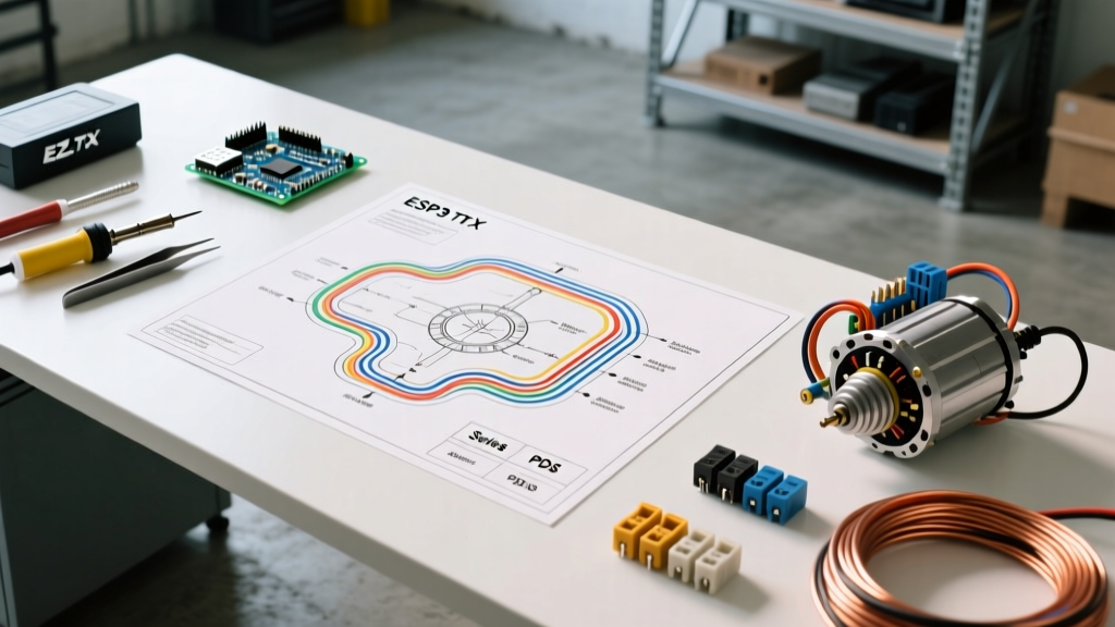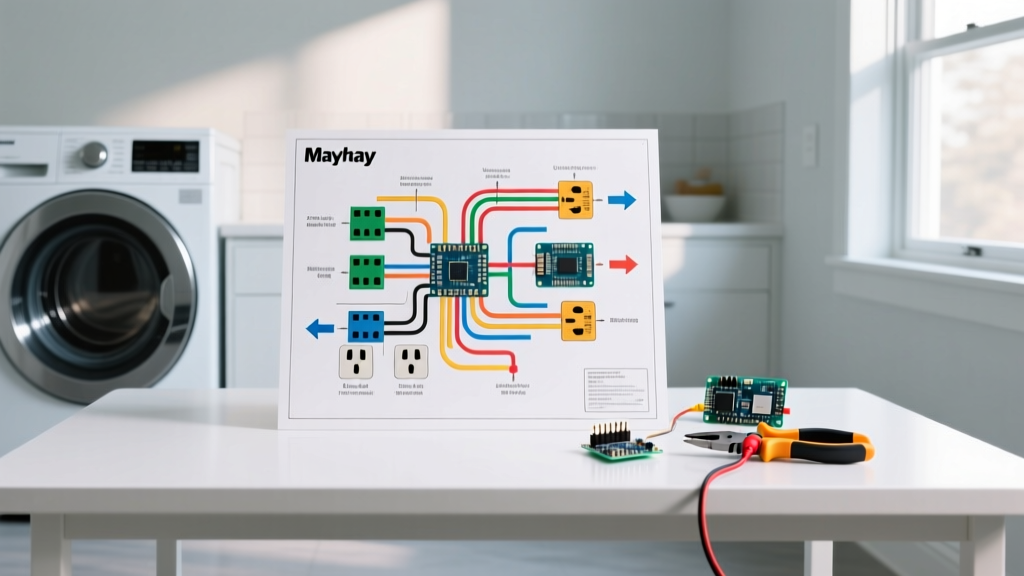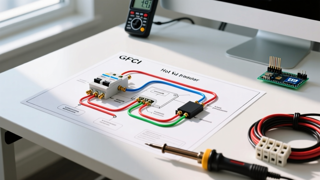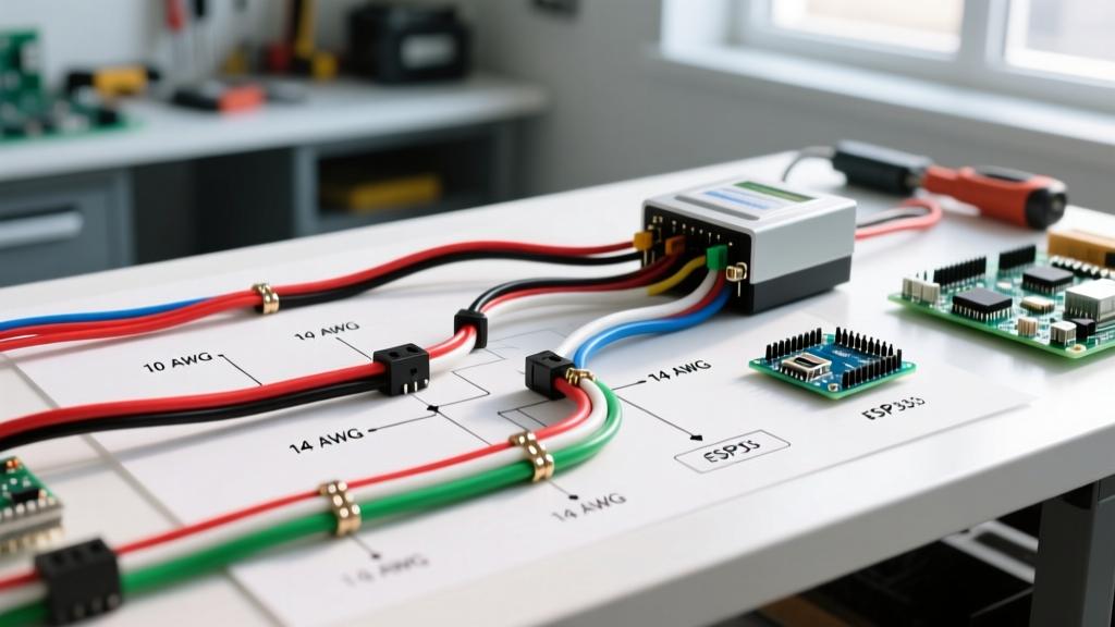

The Critical Role of Wire Gauge and Color Codes in RV Inverter Systems
As recreational vehicles in 2026 increasingly rely on high-capacity lithium iron phosphate (LiFePO4) battery banks and 3000W+ pure sine wave inverters for off-grid living, the margin for electrical error has vanished. When reviewing an inverter wiring diagram for RV applications, the schematic is only half the battle. The physical execution—specifically wire gauge selection, voltage drop management, and strict adherence to color code standards—dictates whether your system will run efficiently or become a severe fire hazard.
This guide bridges the gap between theoretical schematics and physical installation, providing exact wire sizing matrices, ABYC and NEC color code standards, and real-world failure modes for modern RV inverter setups.
DC Side (12V/24V): Wire Gauge Sizing and Ampacity
The DC side of an RV inverter carries massive current. A 3000W inverter operating on a 12V nominal system will pull approximately 250 amps continuously, and up to 350 amps during surge loads (like starting a microwave compressor). Undersizing this wire leads to catastrophic voltage drop, causing the inverter to trigger low-voltage disconnects (LVD) or melt the wire insulation.
12V Inverter DC Wire Sizing Matrix (Pure Copper, 90°C Rating)
The following table assumes a 3% maximum voltage drop, which is the strict threshold for sensitive inverter logic boards. Distances are measured as the one-way run from the battery busbar to the inverter terminal.
| Inverter Size (Watts) | Max Continuous Draw | Min Wire Gauge (AWG) | Max One-Way Distance (3% Drop) | Required Overcurrent Protection |
|---|---|---|---|---|
| 1000W | 90A | 2 AWG | 12 feet | 125A Class T / ANL |
| 2000W | 180A | 1/0 AWG | 10 feet | 250A Class T |
| 3000W | 275A | 2/0 AWG | 8 feet | 350A Class T |
| 4000W (24V System) | 185A | 1/0 AWG | 15 feet | 250A Class T |
2026 Market Warning: Avoid CCA Wire
Always purchase 100% fine-strand pure copper wire (Type 3137 or Class K). Copper-Clad Aluminum (CCA) wire has flooded the RV market due to its lower cost (often 40% cheaper than pure copper). However, CCA has roughly 30% less ampacity and is highly brittle under the vibration of highway travel. Using CCA for high-amperage inverter runs is a leading cause of RV electrical fires.
DC Color Code Standards: ABYC vs. Legacy RV Practices
One of the most confusing aspects of RV wiring is the clash between automotive legacy standards and modern marine/RV electrical codes. For high-current inverter wiring, you must follow the American Boat and Yacht Council (ABYC) E-11 standards, which the RV Industry Association (RVIA) increasingly adopts for high-voltage and high-current DC systems.
- Positive (Ungrounded DC): Red (Mandatory across all standards).
- Negative (DC Ground/Return): Black or Yellow. ABYC prefers black or yellow to prevent confusion with AC neutral. Note: Older RVs often use White for DC ground. If integrating a new inverter into an old chassis, label the white DC ground wires heavily to avoid crossing them with 120V AC neutral.
AC Side (120V): NEC Compliance and Color Codes
The AC output of your inverter connects to your RV's sub-panel or automatic transfer switch (ATS). Because this side operates at 120V AC, it falls under the jurisdiction of the National Electrical Code (NEC / NFPA 70). Standard residential Romex (NM-B) or stranded THHN in flexible conduit is used here.
Standard 120V AC RV Color Codes
- Hot (Line 1): Black (Connects to the inverter AC-Out 'L' terminal and the main breaker).
- Neutral: White (Connects to the inverter AC-Out 'N' terminal and the neutral busbar).
- Equipment Ground: Green or Bare Copper (Connects to the inverter chassis ground lug and the ground busbar).
Gauge Sizing: For a 3000W inverter (capable of ~25A continuous output), you must use a minimum of 10 AWG copper wire for the AC side, protected by a 30A double-pole or single-pole breaker, depending on your RV's split-phase or single-phase panel configuration.
Real-World Scenario: Wiring a Victron MultiPlus-II 12/3000
Let's apply these standards to a premium, industry-standard setup in 2026: the Victron MultiPlus-II 12/3000/120-50 (retailing around $1,550). This unit features PowerAssist and requires robust wiring to handle its 50A internal transfer switch.
Step-by-Step Physical Execution
- DC Positive Run: Run 2/0 AWG pure copper, fine-strand red wire from the positive lithium busbar to the inverter positive terminal.
- Overcurrent Protection: Install a Blue Sea Systems 5112 350A Class T fuse within 18 inches of the positive busbar. Class T is mandatory for LiFePO4 batteries due to their high short-circuit current; standard ANL fuses lack the Ampere Interrupting Capacity (AIC) to safely stop a lithium thermal event.
- DC Negative Run: Run 2/0 AWG black wire from the negative busbar to the inverter negative terminal. Include a 500A/50mV DC shunt (like the Victron SmartShunt) on this negative line to monitor state-of-charge.
- Crimping: Use a hydraulic crimper with the exact 2/0 AWG die. Do not use a hammer crimper. Seal the connection with 3M FP-301 adhesive-lined heat shrink to prevent moisture ingress and copper oxidation.
- AC Wiring: Use 10/3 AWG stranded marine-grade cable (Black, White, Green) from the inverter's AC-Out to the RV's main AC breaker panel.
Common Failure Modes and Edge Cases
Even with a perfect schematic, physical installation errors cause 90% of inverter failures. Watch out for these specific edge cases:
| Failure Mode | Symptom | Technical Root Cause & Solution |
|---|---|---|
| Inverter Shuts Off Under Load | Microwave starts, then inverter alarms and powers down. | Voltage Drop: Wire gauge is too small or distance is too long, causing voltage at the inverter terminals to drop below 10.5V. Upgrade to 2/0 AWG or move batteries closer. |
| Melted Terminals / Fire | Burning plastic smell near battery bank. | High-Resistance Crimp: Wire strands were nicked during stripping, or the crimp was loose. Use a proper wire stripper (not pliers) and verify crimp pull-strength. |
| AC GFCI Trips Randomly | RV bathroom or kitchen outlets won't reset. | Neutral-Ground Bond: The inverter's internal neutral-ground relay is conflicting with the RV's hardwired neutral-ground bond in the sub-panel. Ensure the sub-panel neutral and ground bars are isolated. |
The Importance of Torque Specifications
In 2026, high-end inverters like the Victron MultiPlus or Xantrex Freedom X specify exact torque settings for their terminal bolts (typically 10 to 12 Nm for 2/0 AWG lugs). Hand-tightening with a standard wrench often results in connections that vibrate loose over 10,000 miles of travel. Always use a calibrated torque screwdriver or wrench. Apply a small amount of NO-OX-ID A-Special electrical grease to the copper lugs before torquing to prevent galvanic corrosion between the copper lug and the inverter's tin-plated brass busbar.
Frequently Asked Questions (FAQ)
Can I use welding cable for my RV inverter?
Yes, but with caveats. Welding cable is highly flexible and uses fine strands, which is excellent for RV vibration. However, standard welding cable insulation is often not rated for the high heat or chemical resistance required in engine bays or tight battery compartments. Look for UL-listed welding cable or specifically rated battery cable (SGX or SAE J1127).
Do I need to ground the inverter chassis to the RV frame?
Yes. According to both NEC and ABYC guidelines, the inverter's dedicated chassis ground lug must be connected to the vehicle's main grounding point or a dedicated ground busbar that ultimately ties to the RV chassis. This ensures that an internal AC short to the chassis will trip the breaker rather than electrifying the RV's exterior skin. Use a minimum of 8 AWG green wire for this chassis bond on a 3000W unit.
Where can I find the most reliable reference for marine and RV DC wiring?
For comprehensive, free documentation, the Victron Energy Wiring Unlimited guide is widely considered the gold standard in the mobile power industry. It covers complex multi-inverter setups, grounding topologies, and exact torque specifications that apply universally across RV and marine applications.