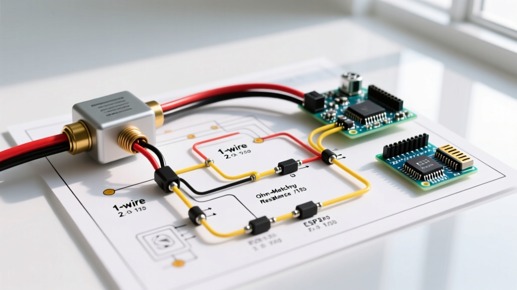

Pre-Installation: Decoding Fuel Sender Ohm Ranges
Before cutting, crimping, or routing a single wire, the most critical step in planning your installation is matching the resistance curve of the sender to your gauge. A mismatch here will result in a gauge that reads backward, pegs at full, or never moves past half. Modern digital gauges and NMEA 2000 converters can be programmed, but analog and standard digital dash gauges require exact hardware matching.
When reviewing a wiring diagram for fuel sending unit integration, the electrical topology is only half the battle; the ohmic range dictates the signal logic. Below is the definitive reference table for standard industry ranges as of 2026.
| Application / Region | Empty (Ohms) | Full (Ohms) | Common Brands / Models |
|---|---|---|---|
| Standard US Marine | 240 | 33 | Wema, KUS, Faria |
| European Marine | 0 | 190 | VDO, Continental |
| US Automotive (GM/Chrysler) | 0 | 90 | ACDelco, Spectra Premium |
| US Automotive (Ford Legacy) | 10 | 180 | Motorcraft, Tanks Inc. |
| VDO Standard (Euro Auto) | 10 | 180 | VDO, Siemens |
Pro Tip: Always test a new sending unit on the bench with a multimeter (like a Fluke 87V) before dropping it into the tank. Sweep the float arm slowly from empty to full. If you see micro-interruptions (the meter flashes 'OL' or jumps erratically), the wiper track is defective. Return it immediately.
Core Topologies: Interpreting the Wiring Diagram for Fuel Sending Unit Circuits
Fuel level senders are essentially variable resistors (potentiometers) connected to a mechanical float arm. The wiring topology changes based on the tank material, vehicle type, and safety requirements. Here are the three standard configurations you will encounter.
1. The 1-Wire Grounding Setup (Standard Automotive)
This is the most common configuration for steel or aluminum automotive fuel tanks. The tank itself acts as the ground path back to the chassis.
- Sender Terminal (Signal): Connects to the Gauge 'S' (Sender) terminal via a single insulated wire.
- Sender Body (Ground): The physical mounting flange of the sender grounds directly to the metal fuel tank.
- Tank Ground: A dedicated 14 AWG ground strap must connect the fuel tank to the vehicle chassis to complete the circuit.
Warning: Never rely solely on the fuel filler neck or fuel lines for the tank ground. Vibration and rubber isolation bushings will break continuity, causing the gauge to read 'Empty' constantly.
2. The 2-Wire Isolated Ground (Marine & Composite Tanks)
With the rise of polyethylene and composite fuel tanks in marine and RV applications, the 1-wire system is obsolete. Furthermore, the 2026 updates to the ABYC E-11 Standards heavily emphasize isolated grounds for fuel systems to prevent stray current corrosion and spark hazards.
- Sender Signal Terminal: Routes to the Gauge 'S' terminal.
- Sender Ground Terminal: A dedicated insulated wire routes directly back to the Gauge 'G' (Ground) terminal or a dedicated negative bus bar.
- Isolation: The sender flange is isolated from the tank using a nitrile rubber gasket and nylon shoulder washers on the mounting screws.
3. The 3-Wire Setup with Low-Level Alarm
Common in heavy-duty diesel applications and marine day-tanks, this sender includes a secondary internal switch that triggers at a specific low-fuel threshold (usually 10% capacity).
- Wire 1 (Signal): Variable resistance to the main gauge.
- Wire 2 (Ground): Shared or isolated ground for the wiper circuit.
- Wire 3 (Alarm Switch): Connects to a dashboard warning light or an engine ECU alarm input. This wire receives 12V only when the float drops below the alarm threshold, closing the internal reed switch.
Wire Gauge Selection & EMI Routing Strategy
Fuel sending units operate on low-voltage DC reference signals (typically 5V to 12V depending on the gauge regulator). Because the signal is analog resistance, it is highly susceptible to voltage drop and Electromagnetic Interference (EMI).
According to SAE J1128 and UL 1426 marine standards, you must select the correct wire type and gauge to prevent gauge flutter and inaccurate readings.
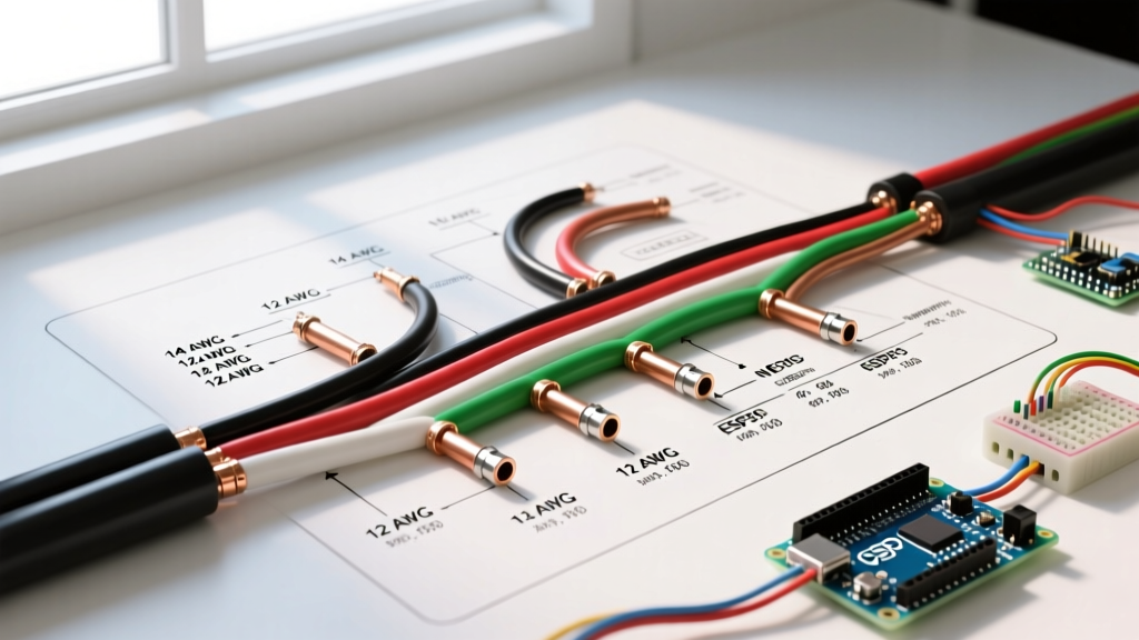
- Wire Gauge: Use 16 AWG for runs under 10 feet. For runs between 10 and 20 feet (common in large motorhomes and yachts), step up to 14 AWG to mitigate voltage drop.
- Wire Type: Use stranded, tinned copper wire (UL 1426) for marine environments. Bare copper will oxidize at the crimp terminals, introducing unwanted resistance that the gauge will interpret as a lower fuel level.
- EMI Routing: Never route the fuel sender signal wire parallel to ignition coil wires, alternator output cables, or VFD motor drives. If crossing high-current cables is unavoidable, cross them at a strict 90-degree angle.
- Twisted Pair: For 2-wire isolated setups, twist the signal and ground wires together (one twist every 2 inches). This creates a common-mode choke effect that cancels out alternator whine and EMI noise.
Step-by-Step Installation & Calibration Checklist
Follow this precise sequence to ensure a leak-free, electrically sound installation. When sourcing components, premium Wema USA Fuel Sensors or KUS stainless steel units typically cost between $45 and $95, a worthwhile investment over cheap $20 zinc-alloy alternatives that corrode within a year.
- Bench Test the Sender: Measure resistance at the empty and full stops. Verify it matches your gauge's expected ohm range.
- Measure Tank Depth: Measure from the mounting flange surface to the absolute bottom of the tank. Subtract 1/2 inch to 1 inch to prevent the float from dragging on the tank floor or picking up sediment.
- Trim the Arm (if adjustable): Cut the stainless steel float arm to the calculated length using a fine-tooth hacksaw. File the edges smooth to prevent puncturing the float bulb.
- Prepare the Flange: Clean the tank mounting surface with isopropyl alcohol. Apply a thin bead of Permatex Marine Grade Sealant (Part #567) if using a metal-to-metal SAE flange, or seat the nitrile O-ring dry if specified by the manufacturer.
- Torque the Hardware: For standard SAE 6-bolt flanges, tighten in a star pattern to 15-20 in-lbs. Over-torquing will warp the flange and cause capillary leaks.
- Continuity Check Before Filling: Connect the wiring harness. Turn the ignition to 'ON' (engine off). Manually push the float arm up and down while a helper watches the dash gauge. The movement should be smooth with no dead spots.
- Final Seal: Apply dielectric grease (like MG Chemicals 846) to all spade terminals and ring terminals before tightening to block moisture ingress.
Diagnostic Edge Cases & Failure Modes
Even with a perfect wiring diagram for fuel sending unit execution, environmental and mechanical factors can introduce faults. Here is how to diagnose the most common edge cases:
Gauge Reads 'Full' When Tank is Empty
The Cause: In a standard 1-wire setup, a broken signal wire or a corroded sender terminal results in infinite resistance (Open Circuit). Most analog gauges interpret infinite resistance as 'Full' (or peg the needle past the max stop).
The Fix: Disconnect the signal wire at the gauge. Momentarily jumper the 'S' terminal to ground. If the gauge drops to 'Empty', the wiring and gauge are fine; the fault is at the sender or the wire is broken mid-run.
Gauge Fluttering at High RPM
The Cause: EMI interference from the ignition system, or a failing voltage regulator on the back of the analog gauge dropping below 5V under heavy alternator load.
The Fix: Install a 12V-to-12V isolated DC-DC converter to power the gauge, or upgrade to a digital stepper-motor gauge which utilizes an internal microcontroller to filter out analog noise and average the signal over a 2-second rolling window.
Sender Stuck at Half-Tank
The Cause: The internal wiper track has worn out or accumulated sulfur deposits from modern ethanol-blended fuels, creating a 'dead zone' in the middle of the resistance card. Alternatively, internal tank baffling is physically blocking the float arm's travel.
The Fix: Remove the sender and inspect the resistance card. If the carbon or wire-wound track is visibly worn or pitted, the unit must be replaced. Cleaning with contact cleaner is only a temporary fix that usually fails within 30 days.