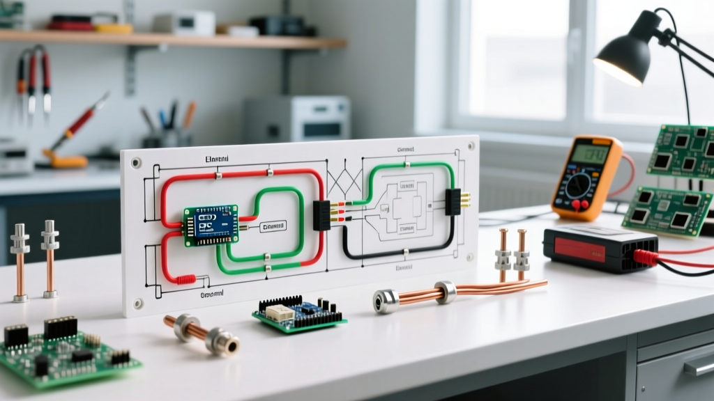

Reading Your Electric Fence Wiring Diagram: The Core Loop
Designing a high-voltage agricultural or perimeter security barrier requires more than simply stringing wire and plugging in a box. A proper electric fence wiring diagram must account for soil resistivity, lightning surge diversion, and strict adherence to electrical codes. As of 2026, modern smart energizers can output upwards of 50+ stored joules, making code compliance and safety protocols non-negotiable to prevent fire hazards, equipment destruction, and stray voltage litigation.
The fundamental circuit of an electric fence is a closed loop. The energizer pushes a high-voltage, low-amperage pulse (typically 110 microseconds in duration) down the live wire. When an animal or intruder touches the wire, the current travels through their body into the soil. From the soil, the current must travel back to the energizer’s ground rods via the earth, completing the circuit. If the grounding system is undersized or improperly wired, the fence will fail to deliver an effective shock, regardless of the energizer's output capacity.
The Grounding System: NEC Article 250 & UL 69 Compliance
The most common point of failure—and the most frequent source of code violations—in any electric fence wiring diagram is the grounding system. Underwriters Laboratories (UL 69) and local adaptations of the National Electrical Code (NEC) dictate strict parameters for how these systems interact with the earth and nearby utility infrastructure.
The 20-Foot Separation Mandate
According to safety standards governing fence controllers, the grounding system for your electric fence must be physically separated from any utility grounding system (including your home’s meter base, telephone grounds, and municipal water pipe grounds) by a minimum of 20 feet (approx. 6 meters).
Code Warning: Failing to maintain this separation can result in the fence energizer backfeeding high-voltage pulses into your home’s AC wiring during a fault or lightning strike, potentially destroying household appliances and creating a severe shock hazard at your utility meter. For comprehensive premises wiring rules, refer to the NFPA 70 National Electrical Code guidelines.
Ground Rod Specifications and Installation
Do not use rebar, T-posts, or copper plumbing pipes as ground rods. Code-compliant diagrams require UL-listed ground rods. For a standard 10-joule to 30-joule energizer, you need a minimum of three ground rods. For high-output models (40+ joules), plan for five to eight rods.
- Material: 5/8-inch x 8-foot copper-clad steel rods (e.g., Galvan Industries or ERICO).
- Spacing: Rods must be spaced at least 10 feet apart in a linear trench.
- Connections: Use heavy-duty, corrosion-resistant brass or bronze ground rod clamps. Never use aluminum clamps on copper or galvanized rods due to galvanic corrosion.
- Wire: Connect the rods using continuous, unspliced 12.5-gauge high-tensile galvanized wire or insulated 20,000V hook-up cable.
Mains-Powered vs. Solar Energizer Wiring Matrix
When drafting your electric fence wiring diagram, the power source dictates your infrastructure. Below is a comparison of wiring requirements for high-output mains units versus portable solar setups.
| Feature | Mains-Powered (e.g., Gallagher M5800i) | Solar/Battery (e.g., Parmak DF-SP-LI) |
|---|---|---|
| Stored Joules | 55 Joules | 2.5 Joules |
| AC Wiring Req. | Dedicated 15A/120V GFCI Circuit | N/A (12V DC internal) |
| Enclosure | NEMA 3R Weatherproof Steel Box | Integrated UV-Plastic Housing |
| Ground Rods | 6 to 8 rods (8ft each) | 1 to 2 rods (4ft to 8ft) |
| Avg. 2026 Cost | $650 - $800 (Unit + Installation) | $300 - $380 (All-in-One) |
Mains AC Wiring: Conduit, Breakers, and Enclosures
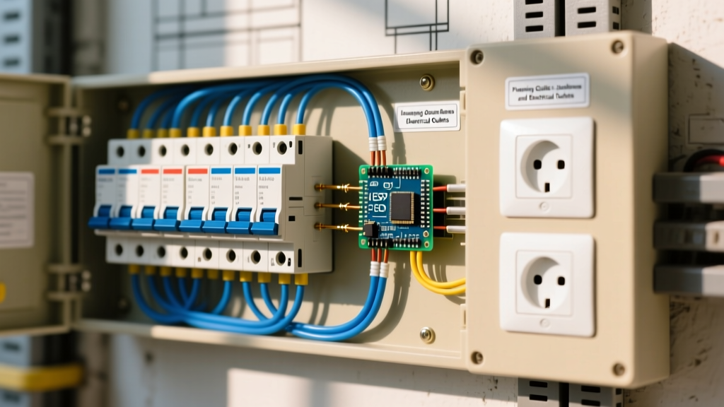
If your diagram includes a 110V/240V mains-powered energizer, the AC supply wiring must adhere to NEC Article 300 for wiring methods. You cannot simply run an outdoor extension cord to the fence controller.
- Breaker Panel: Install a dedicated 15-Amp single-pole breaker in your main service panel. While not always strictly mandated by code for agricultural outbuildings, a GFCI (Ground Fault Circuit Interrupter) breaker is highly recommended to protect against moisture-induced ground faults.
- Conduit Run: Run 12 AWG THHN copper wire through 1/2-inch Schedule 40 PVC conduit buried at least 18 inches deep (or 24 inches if crossing vehicular paths).
- Termination: Terminate the conduit into a NEMA 3R rated weatherproof enclosure (such as the Taymac MM410W). The energizer should be mounted inside or directly adjacent to this enclosure to protect the 120V AC connection from rain and UV degradation.
Lightning Diversion and Surge Protection
Lightning strikes to an electric fence are a leading cause of energizer failure and barn fires. A code-compliant electric fence wiring diagram must include a dedicated lightning diverter installed before the fence wire enters the energizer.
Devices like the Gallagher G2000 Lightning Diverter utilize a spark-gap mechanism. When a massive voltage spike (millions of volts) hits the fence line, the diverter arcs the energy across the gap and sends it directly into the earth, bypassing the sensitive PCB components inside the energizer.
Diverter Installation Rules:
- Mount the diverter outside the energizer enclosure or in a well-ventilated area (the arc creates ozone and minor heat).
- Run a separate, dedicated ground wire from the diverter to its own independent ground rod.
- Do not tie the diverter ground rod into the main energizer ground system; keep it at least 10 feet away to prevent the surge from jumping between the ground wires.
Fire Safety: Wire Spacing and Vegetation Protocols
Electrical arcs igniting dry brush is a severe liability. The Department of Primary Industries and Regional Development (DPIRD) and local fire marshals emphasize specific wiring geometries to mitigate fire risks.
- Wire Spacing: For high-tensile wire, maintain a minimum spacing of 4 to 5 inches between live wires. If wires are too close, wind-induced swaying can cause them to arc, creating a continuous plasma spark that will ignite dry grass.
- Insulators: Use high-density polyethylene (HDPE) or porcelain insulators. Avoid cheap, recycled plastics that become brittle and crack under UV exposure, allowing the wire to rest against wooden posts and start smoldering fires.
- Pulse Rate: Modern 2026 energizers feature 'vegetation management' modes that alter the pulse shape, but you must still maintain a 4-foot clear vegetation buffer on both sides of the fence line in fire-prone zones.
Code Compliance FAQ
Do I need a permit to install an electric fence?
For agricultural and livestock fencing, permits are rarely required at the county level. However, if you are installing a perimeter security fence in a residential or suburban zone, local zoning ordinances and homeowner associations (HOAs) heavily regulate fence height, warning sign placement (required every 50 feet), and proximity to property lines. Always check with your local building authority.
Can I ground my electric fence to my house's copper water pipe?
Absolutely not. This is a severe code violation and a massive safety hazard. Tying the fence ground to a utility ground will send 5,000+ volt pulses into your home's plumbing and electrical grounding system, risking electrocution to anyone touching a faucet or appliance chassis. Always use dedicated, isolated ground rods.
What gauge wire should I use for the fence line?
For permanent, high-tensile agricultural fences, 12.5-gauge (approx. 2.5mm) Class 3 galvanized steel wire is the industry standard. It offers excellent conductivity and a breaking strength of roughly 1,800 lbs. For temporary or portable grazing cells, 9-strand polywire with stainless steel or tinned copper filaments is preferred for visibility and ease of transport.