
Introduction to Honeywell HVAC Control Wiring
Interpreting a wiring diagram for Honeywell appliances requires a solid understanding of both 24VAC control logic and line-voltage safety protocols. In 2026, the residential hydronic heating and forced-air markets are heavily dominated by two specific components: the Honeywell Home T6 PRO Smart Thermostat (Model TH6320WF2003) and the legendary Honeywell V8043E1008 Zone Valve. While wireless sensors and AI-driven climate algorithms have evolved, the foundational hardwired connections remain rooted in classic electromechanical principles.
This comprehensive appliance wiring tutorial breaks down the exact terminal designations, transformer sizing calculations, and isolated end-switch logic required to wire these components without blowing control board fuses or causing phantom voltage feedback. Whether you are retrofitting an aging 1990s boiler system or commissioning a new multi-zone radiant floor setup, mastering these diagrams is non-negotiable for system reliability.
CRITICAL SAFETY WARNING: Always disconnect line voltage (120V/240V) at the main service panel before accessing the air handler, boiler control board, or zone valve junction boxes. Use a non-contact voltage tester (NCVT) and a digital multimeter (DMM) to verify zero energy state. Low-voltage (24VAC) circuits can still deliver painful shocks and will instantly destroy smart thermostat logic boards if crossed with line voltage.
Essential Materials and 2026 Component Pricing
Before pulling wire, verify your inventory. Using undersized transformers or stranded wire in low-voltage terminal blocks are the leading causes of premature component failure. Below is the required material matrix for a standard single-zone boiler application with a smart thermostat.
| Component | Model / Specification | 2026 Est. Cost | Technical Notes |
|---|---|---|---|
| Smart Thermostat | Honeywell T6 PRO (TH6320WF2003) | $165 - $190 | Requires dedicated C-Wire (Common) for Wi-Fi stability. |
| Zone Valve | Honeywell V8043E1008 (1/2" Sweat) | $75 - $95 | Includes isolated SPDT end switch for boiler firing. |
| Control Transformer | 50VA, 24VAC (e.g., Honeywell AT87D) | $32 - $45 | Upgraded from 40VA to handle smart thermostat peak loads. |
| Thermostat Wire | 18 AWG Solid Copper, 5-Conductor | $0.45 / ft | NEC Class 2 rated. Do NOT use stranded wire. |
Decoding the Wiring Diagram for Honeywell T6 PRO Thermostats
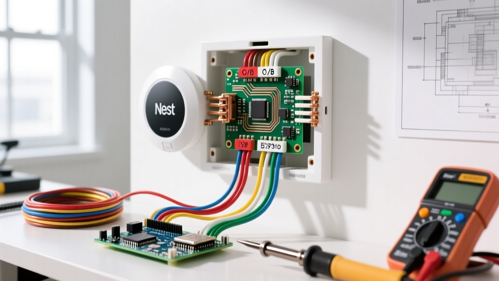
The Honeywell T6 PRO series utilizes a standard UWP (Universal Wall Plate) mounting system. The most common failure mode during DIY installation is misinterpreting the O/B terminal or failing to provide a stable Common (C) wire, which causes the thermostat to 'steal' power through the heating relay, resulting in ghost-clicking relays and premature contactor wear.
Standard 24VAC Terminal Matrix
- R (Red): 24VAC Hot from the transformer secondary. This is the primary power source.
- C (Blue/Black): 24VAC Common. Completes the circuit. Mandatory for the TH6320WF2003.
- W (White): Stage 1 Heat. Sends 24VAC to the heating relay or zone valve motor.
- Y (Yellow): Stage 1 Cooling (Compressor contactor). Not used in boiler-only hydronic systems.
- G (Green): Fan Relay. Energizes the air handler blower. Bypassed in pure radiator/baseboard setups.
Pro-Tip for Wire Preparation: Strip exactly 1/4 inch (6mm) of insulation from 18 AWG solid copper wire. If you expose too much bare wire, the excess copper can bridge the R and C terminals inside the UWP, instantly blowing the 3-amp automotive fuse located on your furnace or boiler control board. Replacement fuses cost $2, but a short circuit can occasionally arc and damage the board's micro-traces, leading to a $350+ control board replacement.
Mastering the V8043E Zone Valve End Switch Logic
The most complex part of any wiring diagram for Honeywell hydronic systems is the V8043E zone valve. This valve contains two completely isolated electrical circuits: the motor circuit and the end switch circuit. Understanding the Single Pole Double Throw (SPDT) microswitch inside the valve powerhead is the key to proper boiler sequencing.
The Two Isolated Circuits
- The Motor Circuit (Yellow Leads): The two yellow wires connect to the 24VAC power supply. One yellow wire connects to the C (Common) side of the transformer, and the other connects to the W (Heat) terminal on the thermostat. When the T6 PRO calls for heat, it closes the internal relay, sending 24VAC across the yellow wires. The synchronous motor opens the brass valve (taking approximately 10 to 15 seconds).
- The End Switch Circuit (Red, White, Blue Leads): This is an isolated dry contact switch. It does not carry 24VAC from the thermostat transformer. Instead, it acts as a mechanical gatekeeper for the boiler's internal 120V or 24V firing circuit.
- Terminal 1 (Common): The pivot point of the microswitch.
- Terminal 2 (Normally Closed): Connected to Terminal 1 when the valve is closed.
- Terminal 3 (Normally Open): Connects to Terminal 1 ONLY when the valve is fully open.
Wiring Sequence: To fire the boiler, you must wire the boiler's "TT" (Thermostat) or "Aquastat" terminals through Terminal 1 and Terminal 3. This ensures the boiler burner will never ignite until the physical brass valve has opened, preventing catastrophic pressure spikes and boiling water inside a blocked heat exchanger.
Transformer Sizing: The 2026 Smart Home Calculation
Historically, HVAC technicians installed 40VA transformers for single-zone systems. However, modern smart thermostats like the T6 PRO draw significantly more current during Wi-Fi transmission bursts, screen wake-ups, and OTA firmware updates. According to the Air Conditioning Contractors of America (ACCA) technical guidelines, control circuits should be sized with a 20% overhead margin.
VA (Volt-Ampere) Load Calculation
- Honeywell V8043E Motor: 0.32 Amps × 24V = 7.68 VA
- Honeywell T6 PRO (Peak Load): ~0.8 Amps × 24V = 19.2 VA
- Standard 24V Relay (if used): ~0.15 Amps × 24V = 3.6 VA
- Total Calculated Load: 30.48 VA
- Required Transformer (with 20% margin): 30.48 × 1.2 = 36.5 VA
While a standard 40VA transformer technically covers this load, upgrading to a 50VA transformer (approx. $38) is highly recommended in 2026 to prevent voltage sag below 20VAC, which can cause the T6 PRO to reboot endlessly during high-latency network handshakes.
Advanced Troubleshooting Matrix
When the system fails to operate, avoid guessing. Use a digital multimeter set to AC Voltage (VAC) to diagnose the exact point of failure. Below are the most common edge cases encountered in the field.
| Symptom | Multimeter Test Points | Expected Reading | Actual Reading & Diagnosis |
|---|---|---|---|
| T6 PRO screen is blank | R to C at UWP | 24.0 - 28.0 VAC | 0 VAC: Blown 3A fuse on control board or broken 18 AWG wire. 12 VAC: Failing transformer or severe voltage drop from undersized wire. |
| Valve hums but won't open | Across Yellow Wires | 24.0 VAC | 24 VAC present: Synchronous motor is seized or internal gear train is stripped. Replace V8043E powerhead. 18 VAC: Phantom voltage from a leaking solid-state relay; install a 10k ohm bleeder resistor. |
| Boiler fires, but pipes stay cold | End Switch (Term 1 to 3) | 0 Ohms (Closed) | Open Loop (OL): Valve motor opened, but the internal SPDT microswitch failed to engage. Replace powerhead assembly. |
NEC Code Compliance and Wire Routing
When routing the 18 AWG thermostat wire alongside 120V appliance feeds, strict adherence to the National Electrical Code is required. According to NFPA 70 (NEC) Article 725, Class 2 low-voltage circuits must be physically separated from Class 1 line-voltage circuits by a minimum of 2 inches, or separated by a continuous and firmly fixed non-conductive barrier.
Never run 18 AWG thermostat wire inside the same conduit or knock-out hole as 12/2 or 14/2 Romex. Electromagnetic interference (EMI) from line-voltage loads can induce phantom voltages in the low-voltage wire, causing the Honeywell T6 PRO to register false temperature readings or accidentally trigger the heating relay. Always use separate jacketed cables and secure them with distinct staple lines, maintaining a 4-inch clearance when crossing line-voltage wires at a 90-degree angle.
Final Commissioning Checklist
- Verify 24VAC at the transformer secondary before connecting the T6 PRO.
- Confirm the 3-amp fuse on the boiler control board is intact.
- Manually rotate the V8043E manual opener lever to ensure the brass valve stem is not seized by mineral scale.
- Apply power and force a heat call via the T6 PRO interface.
- Use an infrared thermometer to verify a 15°F to 20°F temperature rise across the boiler heat exchanger within 5 minutes of the end switch closing.
For official schematics and firmware update logs, technicians should always consult the Honeywell Forward Technical Portal to ensure compatibility with advanced multi-stage modulating boilers.