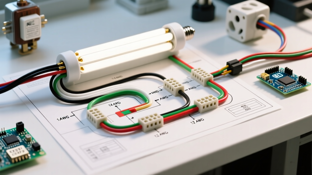

Mastering the Wiring Diagram for Fluorescent Tube Light Installations
While LED retrofits dominate new construction, fluorescent lighting remains a staple in commercial garages, industrial workshops, and older residential builds. Maintaining, repairing, or installing new T8 and T12 fluorescent fixtures requires strict adherence to electrical safety standards. Understanding the standard wiring diagram for fluorescent tube light circuits is only half the battle; selecting the correct wire gauge and strictly following National Electrical Code (NEC) color codes are what separate a safe, long-lasting installation from a dangerous fire hazard.
This comprehensive guide breaks down the anatomy of fluorescent circuits, focusing heavily on wire gauge selection, branch circuit color codes, and ballast-specific wiring nuances. Whether you are wiring a single 4-foot shop light or daisy-chaining commercial troffers, these principles apply.
Understanding the Fluorescent Circuit Path
Unlike incandescent bulbs that connect directly to line voltage, fluorescent tubes require a ballast to regulate current and provide the initial high-voltage spike needed to ignite the mercury vapor inside the tube. The electrical path flows as follows:
- Branch Circuit: Power travels from the breaker panel through the wall switch to the fixture junction box.
- Ballast Input: Line voltage (Hot and Neutral) enters the ballast primary wires.
- Ballast Output: The ballast steps up the voltage and sends it through secondary wires to the tombstones (socket holders).
- Tube Ignition: The electrodes at each end of the tube heat up, ionizing the gas and creating light.
Wire Gauge Selection: Branch Circuit vs. Internal Fixture
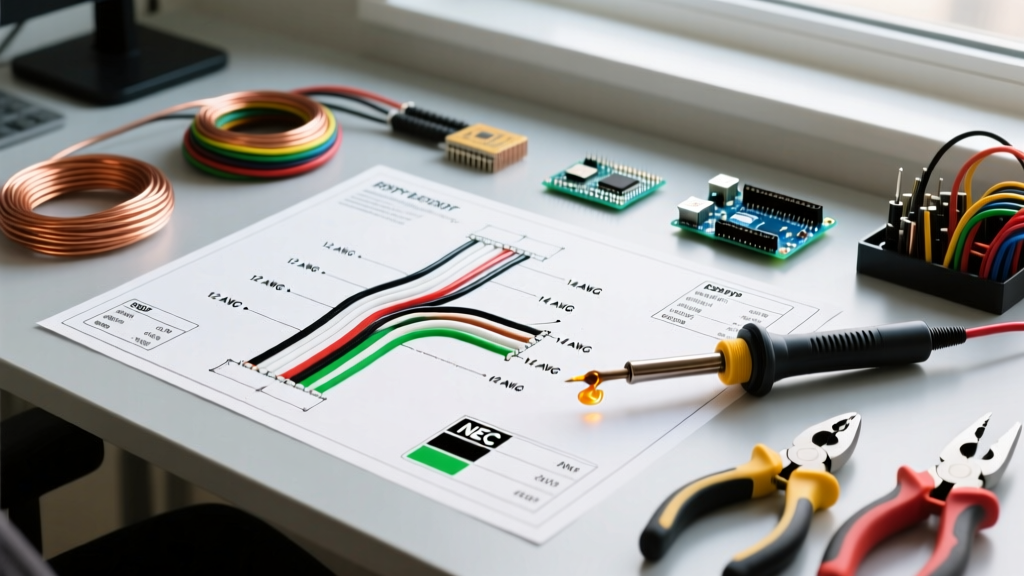
One of the most common mistakes DIYers make when following a fluorescent light wiring diagram is using the wrong wire gauge for the specific segment of the circuit. The NEC, specifically NFPA 70 (National Electrical Code) Article 310, dictates strict ampacity rules based on wire size and insulation type.
Branch Circuit Wire Gauge (Panel to Fixture)
The wire running from your breaker to the fixture must match the overcurrent protection device (breaker). For standard 120V residential and commercial lighting circuits, you will primarily use NM-B (Romex) or THHN in conduit.
| Circuit Breaker | Wire Gauge (AWG) | Max Continuous Load (80%) | Typical Application |
|---|---|---|---|
| 15 Amp | 14 AWG Solid Copper | 12 Amps (1,440W) | Standard residential shop lights, single fixtures |
| 20 Amp | 12 AWG Solid Copper | 16 Amps (1,920W) | Commercial daisy-chained troffers, heavy-duty garage lighting |
Internal Fixture Wire Gauge (Ballast to Tombstone)
Critical Safety Warning: Never use solid core branch-circuit wire for the internal ballast-to-tombstone connections. The heat generated by the ballast and the vibration of the fixture will cause solid core wire to fatigue, snap, and short out against the metal housing. Always use 18 AWG or 16 AWG stranded copper wire rated for 600V and 105°C (typically TFFN or THHN stranded).Ballast manufacturers like Philips Advance and Keystone pre-wire their secondary leads with 18 AWG stranded wire. If you need to extend these leads to reach distant tombstones in an 8-foot fixture, use matching 18 AWG stranded wire and secure the splice with a grey or blue winged wire nut rated for 18 AWG minimum.
NEC Color Code Standards for Lighting
Adhering to color codes is not just a best practice; it is a legal requirement under NEC Article 200 (Neutral), 210 (Branch Circuits), and 250 (Grounding). Miswiring a ballast due to color confusion is a leading cause of premature ballast failure and electrical shock.
Mains Branch Circuit Colors
- Black (Hot/Line): Carries the 120V ungrounded current from the switch to the ballast's primary black wire.
- White (Neutral): The grounded conductor. Connects to the ballast's primary white wire. Note: Never use a white wire as a switched hot unless it is permanently re-identified with black tape or paint at both ends.
- Bare or Green (Ground): The equipment grounding conductor. Must be bonded to the metal fixture housing and the metal ballast casing using a 10-32 green grounding screw.
Ballast Secondary Output Colors
The colors on the output side of the ballast dictate how the power is distributed to the tube ends. These colors vary slightly depending on whether you are using an Instant Start or Rapid Start ballast.
- Blue: Typically carries the 'hot' output to one end of the first tube.
- Red: Carries the 'hot' output to one end of the second tube (or the opposite end in single-lamp rapid start setups).
- Yellow: The common/neutral return path. In rapid start ballasts, yellow wires often connect to the opposite ends of both tubes to complete the pre-heat circuit.
Always defer to the specific wiring diagram printed on the ballast label, as manufacturers like GE and Sylvania occasionally use different secondary color schemes for high-output (HO) or very high-output (VHO) T12 ballasts.
Magnetic vs. Electronic Ballast Wiring Differences
When interpreting a wiring diagram for fluorescent tube light fixtures, you must first identify the ballast type. The industry has largely transitioned to electronic ballasts, but magnetic ballasts still exist in older facilities.
Magnetic Ballasts (Core & Coil)
Magnetic ballasts require a separate starter for pre-heating the tube cathodes in older T12 fixtures. The wiring diagram includes a starter socket wired in series with the tube filaments. These ballasts are heavy, hum audibly at 60Hz, and operate at lower frequencies, which can cause visible flickering.
Electronic Ballasts (Solid State)
Electronic ballasts operate at high frequencies (20kHz to 60kHz), eliminating flicker and hum. They do not require a separate starter. The wiring is significantly simpler: line voltage in, and high-frequency high-voltage out directly to the tombstones. When upgrading from magnetic to electronic (e.g., installing a Philips Centium ICN-2P32-N), you must bypass and remove the old starter and rewire the tombstones to match the electronic ballast's parallel or series output requirements.
Step-by-Step Wiring Procedure
Follow these actionable steps to ensure a code-compliant and safe installation. For comprehensive safety protocols regarding lockout/tagout and live circuit testing, always refer to OSHA Electrical Safety Guidelines.
- De-energize and Verify: Turn off the 15A or 20A breaker. Use a non-contact voltage tester and a digital multimeter (like a Fluke 117) to confirm zero voltage at the fixture junction box.
- Prepare the Mains Wire: Strip 3/4 inch of insulation from the 14 AWG or 12 AWG NM-B cable. Ensure the bare ground wire is long enough to reach the fixture's green grounding screw.
- Bond the Ground: Attach the bare copper ground to the fixture housing. If the ballast is metal and isolated from the housing by rubber grommets, run a separate 14 AWG ground pigtail from the housing to the ballast casing.
- Connect Line and Neutral: Using an orange or red wire nut (e.g., Ideal 72B Wire-Nut), connect the branch circuit black wire to the ballast black wire. Connect the white to the white. Give each wire a firm tug to ensure a solid mechanical connection.
- Route Secondary Wires: Route the 18 AWG blue, red, and yellow wires through the fixture channel. Keep them separated from the 120V mains wires to prevent inductive interference and insulation breakdown.
- Terminate at Tombstones: Push the stranded wires into the push-in terminals of the shunted or non-shunted tombstones. Crucial Detail: Instant start ballasts require shunted tombstones; rapid start and programmed start ballasts require non-shunted tombstones.
- Final Test: Install the fluorescent tubes, ensuring the pins are fully seated and twisted 90 degrees. Restore power and verify ignition.
Troubleshooting Common Fluorescent Failures
Even with a perfect wiring diagram for fluorescent tube light setups, components degrade. Here is how to diagnose specific failure modes based on your wiring:
Ends Glow, But Tube Won't Strike
The Culprit: This indicates the pre-heat circuit is functioning, but the high-voltage strike is failing. In rapid start systems, check the yellow common wires. If a yellow wire is loose at the tombstone, the circuit cannot complete the return path, preventing the gas from fully ionizing.
Tube Flickers Continuously
The Culprit: Often caused by a failing tube or cold ambient temperatures exceeding the ballast's rating. However, from a wiring perspective, check for 'stray voltage' or a shared neutral issue. If the white neutral wire is undersized or shared with a heavily loaded 20A receptacle circuit, voltage drop can prevent the electronic ballast's microprocessor from stabilizing the arc.
Burn Marks on Tombstone
The Culprit: Arcing due to poor pin contact. This happens when non-shunted tombstones are incorrectly used with instant-start ballasts, or when 18 AWG stranded wire is not fully inserted into the push-in terminal. Replace the tombstone (Leviton 13660 or equivalent) and strip a fresh 1/4 inch of the 18 AWG wire.
Final Thoughts on Code Compliance
Wiring a fluorescent fixture is a precise exercise in managing voltage, current, and heat. By strictly adhering to the NEC color codes, respecting the ampacity limits of 14 AWG and 12 AWG branch circuits, and utilizing the correct 18 AWG stranded wire for internal ballast connections, you ensure a system that is both safe and durable. Always verify your specific ballast manufacturer's schematic before energizing the circuit, as minor variations in secondary wire colors do exist across different production runs.