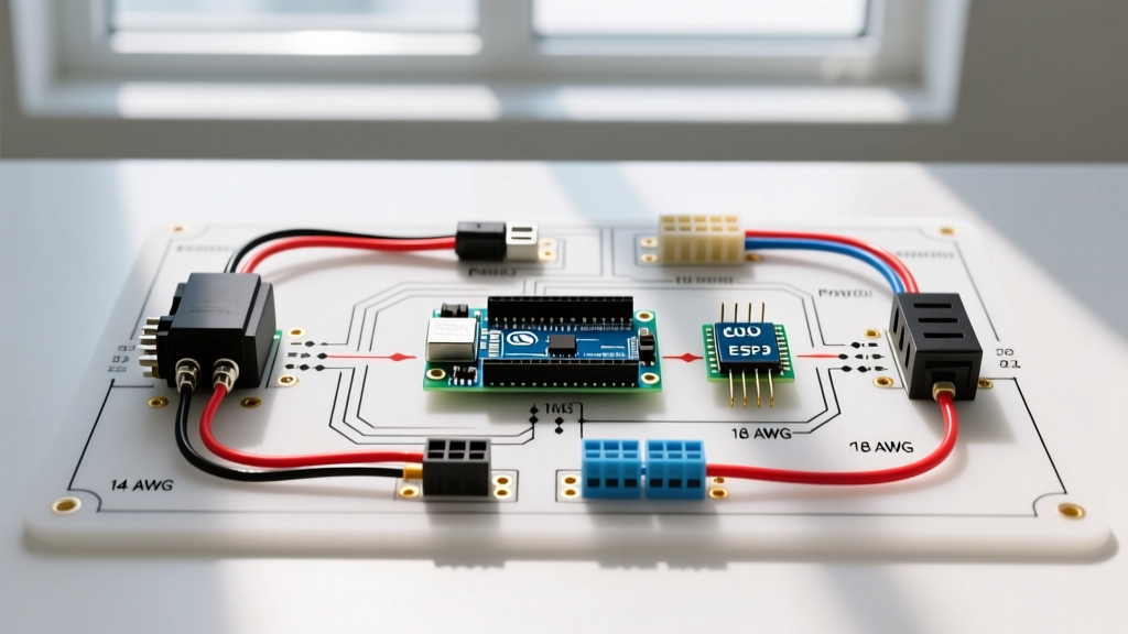

The Motor-Load Parallel: Why Light Bars Need Motor-Grade Wiring
When off-road enthusiasts and heavy machinery operators look for a wiring diagram for a light bar, they often default to standard automotive lighting guides. This is a critical mistake in 2026. Modern high-output LED light bars—such as the 50-inch Baja Designs OnX6 or the Rigid Industries SR-Series PRO—draw between 25 and 40 amps continuously. More importantly, their internal switching power supplies and massive input capacitor banks create an inrush current upon startup that can spike to 300% of the steady-state draw for several milliseconds.
This electrical behavior perfectly mirrors the locked-rotor inrush current of a 12V DC winch motor or a heavy-duty radiator cooling fan. If you wire a high-draw light bar using standard 14 AWG lighting wire and a cheap 10-amp toggle switch, the inrush spike will arc the switch contacts, melt the harness, or trigger the CAN-bus protection protocols on modern UTVs and trucks, shutting down the entire accessory circuit. By applying motor wiring tutorial principles—specifically heavy-duty relay isolation, flyback diode protection, and proper gauge sizing—you ensure a bulletproof, fire-resistant installation.
Essential Bill of Materials (BOM) for a Motor-Grade Harness
To handle the inductive and capacitive loads inherent in high-draw LED arrays, we treat the light bar as a small DC motor. Below is the precise hardware required for a 35-amp continuous draw setup, utilizing SAE J1128 compliant primary cable standards.
| Component | Specification | Estimated 2026 Cost | Purpose |
|---|---|---|---|
| Main Power/Ground Wire | 10 AWG SAE J1128 Copper | $1.15 / ft | Handles 40A continuous with minimal voltage drop. |
| Trigger Circuit Wire | 16 AWG Primary Wire | $0.45 / ft | Carries low-current signal to the relay coil. |
| Power Relay | Bosch-Style 4-Pin 50A (with Diode) | $14.50 | Isolates high-current load from the dashboard switch. |
| Main Circuit Protection | 50A ANL Fuse & Holder | $18.00 | Protects against dead shorts; handles high inrush. |
| Inline Switch | 20A Illuminated Rocker (SPST) | $8.50 | Triggers the relay coil safely. |
Step-by-Step Wiring Diagram for a Light Bar (Relay Isolation)
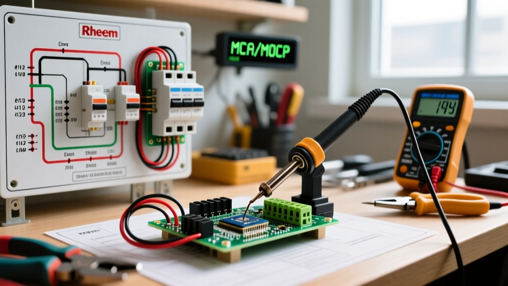
The core of any motor-control circuit is the relay. A standard automotive relay uses a low-current electromagnetic coil to close a high-current mechanical contact. Here is the exact terminal mapping for your wiring diagram:
- Terminal 30 (High-Current Input): Run 10 AWG wire directly from the positive battery terminal. Install the 50A ANL fuse holder within 6 inches of the battery post. This is a non-negotiable DC circuit protection standard to prevent battery fires in the event of a chafed wire.
- Terminal 87 (High-Current Output): Run 10 AWG wire from this terminal to the positive input of the light bar. Use a weather-pack connector with dielectric grease to prevent corrosion on the roof rack or bumper.
- Terminal 85 (Relay Coil Ground): Run 16 AWG wire to a clean, bare-metal chassis ground. Sand away paint and clear coat to ensure a resistance of less than 0.1 ohms.
- Terminal 86 (Relay Coil Trigger): Run 16 AWG wire from your dashboard rocker switch. The switch should be powered by an ignition-switched 12V source (not constant battery power) to prevent parasitic drain.
Expert Insight: The Flyback Diode
Just like a DC motor generates a reverse voltage spike (back-EMF) when powered down, a relay's electromagnetic coil generates a flyback voltage spike when the switch is opened. In modern 2026 vehicles with multiplexed CAN-bus systems, this spike can backfeed into the ECU and cause fault codes. Always use a relay with an internal flyback diode (or wire an external 1N4007 diode across terminals 85 and 86, banded side toward Terminal 86) to clamp this spike.
Advanced Integration: PWM Dimming via Motor Speed Controllers
One of the most valuable crossovers between motor wiring and light bar installation is the use of a Pulse Width Modulation (PWM) DC motor speed controller to act as a variable dimmer. Many premium light bars lack built-in dimming, blasting 10,000+ lumens even when you just need a subtle camp light or trail-running beam.
By wiring a 12V 30A PWM Motor Speed Controller module between the relay's Terminal 87 and the light bar's positive lead, you can achieve flicker-free dimming. The PWM module switches the power at a high frequency (typically 1kHz to 25kHz), which is fast enough that the LED drivers interpret it as a lower continuous voltage rather than a strobe effect.
PWM Dimmer Wiring Sequence:
- Relay Terminal 87 → PWM Module IN+
- Light Bar Positive → PWM Module OUT+
- Light Bar Ground → PWM Module OUT- (and tied to main chassis ground)
- Battery Ground → PWM Module IN-
Warning: Never wire the PWM module on the low-current trigger side (Terminals 85/86). The PWM signal will cause the relay to chatter violently, destroying the mechanical contacts within minutes.
Calculating Voltage Drop for Long Cable Runs
When mounting a light bar on a lifted truck's roof rack or a UTV's roll cage, the cable run from the engine bay battery to the roof can easily exceed 15 feet. According to AWG resistance standards, pushing 35 amps through 15 feet of 12 AWG wire will result in a voltage drop of roughly 1.3 volts. While this seems minor, LED drivers will compensate for lower voltage by drawing more amperage to maintain their wattage output, generating excess heat and potentially tripping your fuse.
Always use the following formula to verify your wire gauge:
Voltage Drop = (2 x L x I x R) / 1000
Where L is length in feet, I is current in amps, and R is the resistance per 1000 ft of your chosen wire gauge. For any run exceeding 12 feet on a 35A light bar, step up to 8 AWG wire for the main power and ground legs to keep the voltage drop below 3% (0.36V on a 12V system).
Troubleshooting Common Motor-Load Failures
If your light bar setup is failing, apply these motor-circuit diagnostic steps:
- Relay Clicking Rapidly (Chatter): This indicates a voltage drop on the trigger circuit (Terminal 86). The relay coil is not receiving a solid 12V, causing it to open and close rapidly. Check your dashboard switch for corroded spade connectors and verify the ignition-switched power source isn't shared with other high-draw accessories.
- Light Bar Flickers at Idle but is Solid at High RPM: Your vehicle's alternator output at idle is dropping below the LED driver's threshold, or your ground wire is undersized. Measure the voltage directly at the light bar's input pins while the engine is idling. If it reads below 11.8V, upgrade your ground wire and ensure you are grounded to the engine block or chassis, not a painted body panel.
- ANL Fuse Blows on Startup but Not During Use: Your fuse is rated for steady-state current but cannot handle the capacitive inrush spike. Switch to a time-delay (slow-blow) fuse or increase the ANL fuse rating by 25% (e.g., from 40A to 50A), provided your wire gauge is rated for the higher amperage.
By treating your high-draw LED light bar with the same respect and engineering rigor as a heavy-duty DC motor, you eliminate the electrical gremlins that plague amateur installations. Proper relay isolation, SAE-compliant wire gauges, and flyback protection ensure your lighting system performs flawlessly in the harshest off-road environments.