
Introduction to Fan Relay Motor Circuits
When bridging low-voltage logic with high-voltage mechanical torque, understanding the wiring diagram for fan relay systems is a foundational skill for any electrical technician or advanced DIYer. In HVAC and industrial ventilation, the fan relay acts as the critical gatekeeper. It receives a low-amperage signal (typically 24V AC from a thermostat or control board) and mechanically closes high-amperage contacts (120V to 240V) to energize the fan motor. Misinterpreting the schematic can lead to welded contacts, burnt-out control boards, or catastrophic motor failure. This guide dissects the anatomy, execution, and troubleshooting of modern fan relay circuits, incorporating the latest 2026 efficiency standards and component specifications.
Core Components in a Modern Fan Circuit
Before tracing the wires, you must identify the specific hardware on the bench. A standard 1/3 HP to 1 HP residential or light-commercial fan circuit relies on four primary components:
- The Relay/Contactor: For loads under 30A, a heavy-duty relay like the Dayton 4GNX1 (24VAC coil, 30A FLA resistive, DPST-NO) is standard. For larger blower assemblies, a 30A or 40A magnetic contactor (e.g., Carrier HN51KC040) is required to handle the inrush current (LRA).
- The Fan Motor: Traditional Permanent Split Capacitor (PSC) motors (like the Fasco A067 1/4 HP) are being rapidly phased out. By 2026, the DOE mandates have pushed the market toward Electronically Commotated Motors (ECMs), such as the Genteq X13 series, which drastically alters how relays are deployed.
- Run Capacitor (PSC Only): A microfarad-rated component (e.g., Titan Pro 5+45 MFD) that provides the phase shift necessary for the start winding. Capacitors must be rated at least 15% higher than the motor's operating voltage.
- Control Transformer: Steps down 240V/120V line voltage to 24V AC for the control logic, typically rated at 40VA to 75VA to handle the inrush current of the relay coil without sagging.
Decoding the Wiring Diagram for Fan Relay Systems
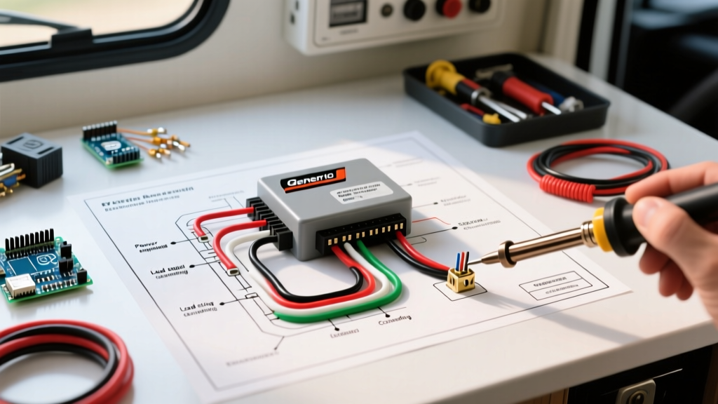
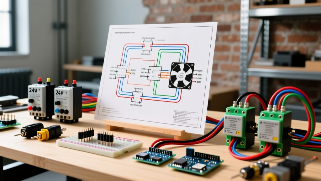
Reading the schematic requires separating the circuit into two distinct halves: the Control Circuit and the Line/Load Circuit. Let us trace a standard 240V PSC fan motor wired through a DPST (Double Pole, Single Throw) relay.
1. The Line and Load Side (High Voltage)
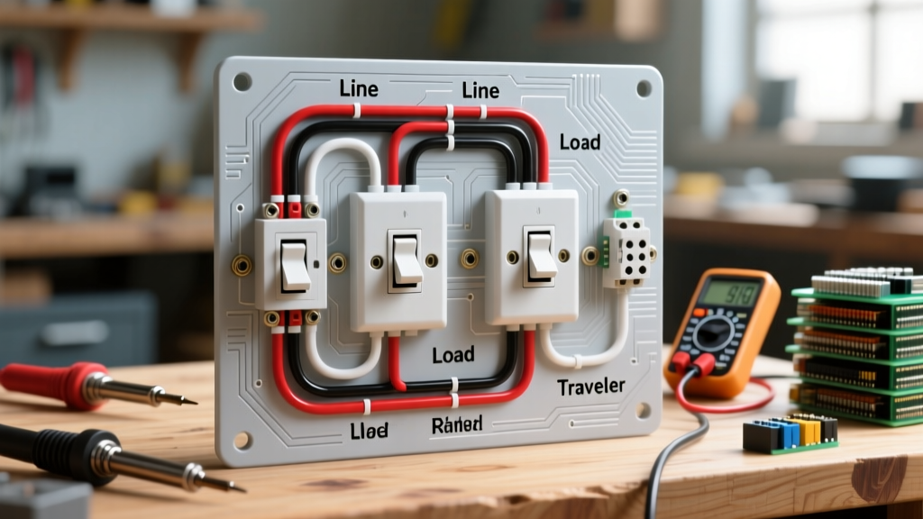
The line side (L1 and L2) receives the main power feed from the breaker panel. In a 240V system, both hot legs pass through the relay contacts. When the coil is de-energized, the physical gap isolates the motor completely from the grid. The load side (T1 and T2) routes power directly to the motor's run winding and the common terminal of the run capacitor. Always use 14 AWG THHN copper wire for 240V circuits up to 15A, ensuring the insulation rating is 600V minimum.
2. The Coil Side (Low Voltage)
The coil terminals (often labeled A1 and A2, or simply two spade terminals on smaller relays) complete the 24V AC circuit. One terminal connects to the 'C' (Common) wire from the transformer. The other connects to the 'G' (Fan) terminal on the thermostat or control board. When the thermostat calls for fan operation, it bridges the 24V 'R' and 'G' circuits, energizing the coil and creating the magnetic field that pulls the high-voltage contacts closed.
Expert Insight: Never wire the high-voltage line through a single pole of a DPST relay while bypassing the second pole. Breaking only one leg of a 240V circuit leaves the motor windings energized at 120V to ground, creating a severe shock hazard and potential for capacitive coupling degradation over time.
Step-by-Step Motor Wiring Procedure
Follow this precise sequence to ensure safety, code compliance, and operational longevity. Always adhere to OSHA's Lockout/Tagout (LOTO) standards before opening any electrical panel.
- Verify Zero Energy State: Use a CAT III or CAT IV rated multimeter to test L1 and L2 at the breaker, and then at the relay line terminals. Confirm 0.0V AC.
- Terminate the Line Side: Strip 3/4 inch of insulation from your 14 AWG THHN wires. Connect L1 and L2 from the disconnect switch to the top terminals of the relay. Torque the terminal screws to the manufacturer's specification (typically 12 to 15 in-lbs for standard 1/4-inch screws).
- Wire the Load Side to the Motor: Run 14 AWG wire from T1 and T2 on the relay. T1 routes to the motor's main run terminal. T2 routes to the common terminal of the run capacitor.
- Integrate the Capacitor (PSC Motors): Connect a 10 AWG or 14 AWG jumper from the capacitor's 'C' (Common) terminal to the motor's start winding. Connect the 'Herm' or 'Fan' terminal on the capacitor to the motor's auxiliary start terminal.
- Land the Control Wires: Use 18 AWG solid copper thermostat wire. Connect the 'C' wire to A1 on the relay coil. Connect the 'G' (switched hot) wire to A2. Secure wires with wire nuts or push-in connectors, ensuring no bare copper is exposed outside the connector.
- Pre-Flight Continuity Check: Before restoring power, set your multimeter to Ohms (Ω). Place probes across L1/T1 and L2/T2. The reading must be infinite (OL). If you read continuity with the coil de-energized, the relay contacts are welded shut; replace the relay immediately.
PSC vs. ECM: How 2026 Efficiency Standards Shift Relay Wiring
The transition to ECM (Electronically Commutated Motors) has fundamentally changed how technicians interpret a wiring diagram for fan relay applications. Under the latest DOE efficiency mandates, ECMs are standard in new residential and commercial HVAC installs.
| Feature | Traditional PSC Motor + Relay | Modern ECM Motor (e.g., Genteq X13) |
|---|---|---|
| High Voltage Routing | Relay breaks both L1 and L2 directly to the motor windings. | Continuous 240V/120V power is supplied to the motor module; relay is often eliminated or used only for a secondary transformer. |
| Control Logic | 24V AC energizes the relay coil. | 24V AC logic signal (from 'G' or 'Y') is sent directly to the ECM microcontroller pins. |
| Speed Control | Requires multiple physical taps on the motor and complex multi-pole relays. | Speed is programmed via dip switches on the module or communicated via digital serial protocols. |
| Failure Mode | Relay contacts weld or coil burns out. | Internal motor module thermistors trip or logic board fails due to voltage sags. |
When wiring an ECM, the 'relay' is often replaced by a simple 24V isolation relay used solely to trigger the control board, which then commands the ECM via low-voltage logic pins. Attempting to switch the 120V/240V main power to an ECM on and off rapidly via a standard contactor will destroy the motor's internal power factor correction capacitors and rectifier bridge.
Advanced Troubleshooting Matrix
When the fan fails to engage, use this matrix to isolate the fault. Ensure your multimeter is set to the correct AC voltage range and that you are referencing a solid ground or the correct common leg.
| Symptom | Multimeter Test Point | Expected Reading | Actual Reading & Diagnosis |
|---|---|---|---|
| Thermostat calls for fan, motor does nothing. | Relay Coil (A1 to A2) | 24V AC | 0V: Open circuit in thermostat wire, blown 3A fuse on control board, or failed transformer. |
| Relay clicks loudly, but motor hums and won't spin. | Relay Load Side (T1 to T2) | 240V AC | 240V Present: Relay is good. Fault is a failed run capacitor (test with capacitance meter) or seized motor bearings. |
| Relay clicks, motor runs, but shuts off after 3 minutes. | Motor Thermal Overload (Internal) | Continuity (0 Ohms) | Infinite (OL): Motor is overheating. Check for restricted airflow, dirty blower wheel, or incorrect voltage tap setting. |
| Motor runs, but relay coil gets excessively hot and smells like ozone. | Transformer Secondary (R to C) | 24V AC to 28V AC | Below 22V: Transformer is undersized for the coil's VA requirement, or there is a partial short in the control wire. |
Code Compliance and Safety Standards
All motor wiring must comply with the National Electrical Code (NEC / NFPA 70). Specifically, Article 430 governs motor branch circuits, requiring that the branch circuit conductors be sized at no less than 125% of the motor's Full Load Amps (FLA). For a fan motor drawing 8A FLA, your wire must be rated for at least 10A, making 14 AWG (rated 15A) the absolute minimum, though 12 AWG is heavily recommended for long runs to mitigate voltage drop.
Furthermore, NEC Article 440 dictates specific requirements for HVAC systems, including the sizing of the disconnect switch. The disconnect must be rated for the specific voltage and have an ampere rating no less than 115% of the compressor or fan motor's rated-load current. Always ensure your relay enclosure is NEMA-rated appropriately for the environment (e.g., NEMA 3R for outdoor condenser fan applications to protect against rain and sleet).
For further reading on control circuit diagnostics and component verification, the technical archives at HVACR School provide excellent visual breakdowns of relay logic and contactor failure modes that complement the theoretical knowledge outlined in the NEC.
Final Verification
Once wiring is complete, restore power and measure the voltage drop across the closed relay contacts (L1 to T1, and L2 to T2). A healthy relay with clean silver-alloy contacts will show a voltage drop of less than 0.05V under load. Any reading above 0.2V indicates pitting, carbon buildup, or loose terminal torque, requiring immediate replacement to prevent a thermal runaway event in your electrical panel.