
Strategic Planning for Trailer Brake Controller Integration
Designing a robust wiring diagram for brake controller integration requires more than simply connecting colored wires to a 7-way blade. Whether you are outfitting a heavy-duty pickup for a gooseneck livestock trailer or wiring a mid-size SUV for a travel trailer, the electrical demands of electric trailer brakes are substantial. A standard 2-axle trailer can draw between 12 to 24 amps under maximum braking load, while a 3-axle setup can easily exceed 35 amps. If your wiring infrastructure is undersized, you will experience severe voltage drop, resulting in weak braking performance and potential overheating of the wire insulation.
As of 2026, modern proportional controllers like the Tekonsha Prodigy P3 (Model 90195) and the Curt Spectrum (Model 51170) utilize pulse-width modulation (PWM) to deliver smooth braking. However, these sophisticated microprocessors are highly sensitive to voltage fluctuations. This installation planning guide breaks down the exact wire gauges, termination standards, and circuit protection strategies required to ensure your braking system meets the rigorous SAE J2807 tow vehicle guidelines for safety and performance.
Component Selection & Current Market Pricing
Before drafting your physical wiring route, select the hardware that matches your gross combined weight rating (GCWR). Universal hardwire kits are necessary for older vehicles, while modern trucks often utilize plug-and-play harnesses (e.g., Tekonsha 3024-P for Ford Super Duty). Below is a snapshot of current industry-standard controllers and their power requirements:
- Tekonsha Prodigy P3 (90195): Retailing around $165, this unit supports up to 4 axles and requires a dedicated 30A circuit for the brake output.
- Curt Spectrum (51170): Priced near $140, this flush-mount OLED controller draws minimal standby current but demands clean 12V DC power to prevent screen flickering and PWM signal degradation.
- Redarc Tow-Pro Elite: At approximately $215, this active proportional controller requires a robust 12V feed and a dedicated chassis ground to function correctly in active braking mode.
Wire Gauge Selection & Insulation Standards
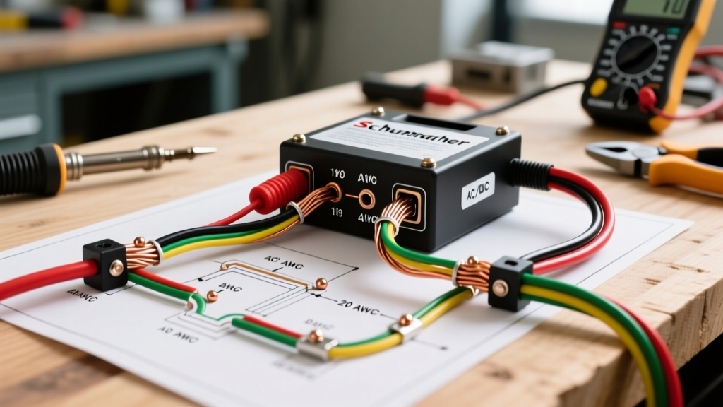
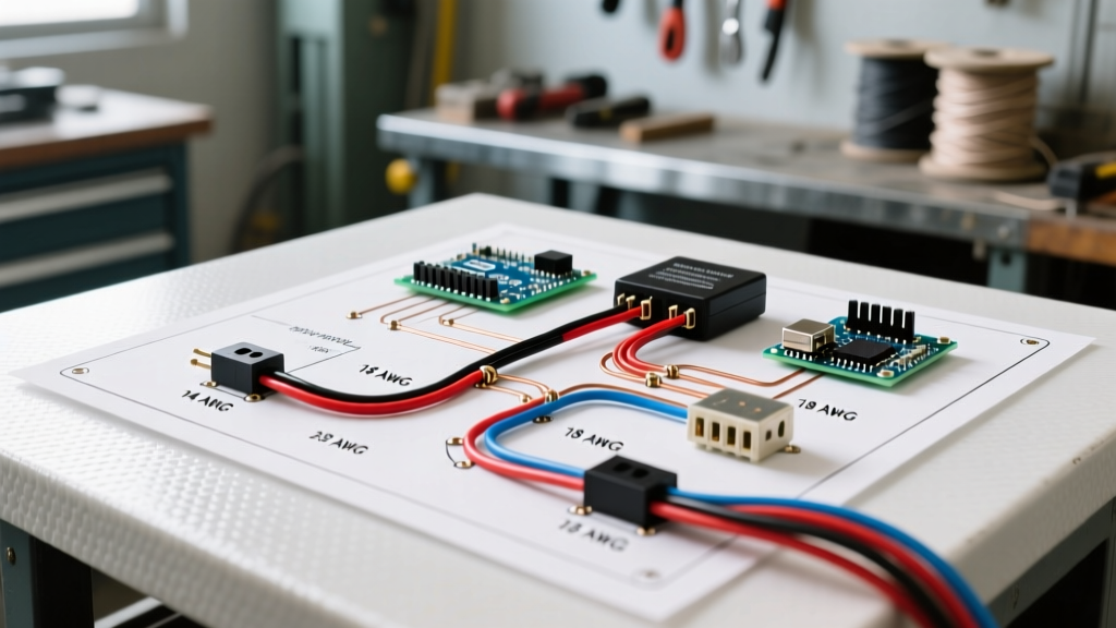
The most critical element of your wiring diagram for brake controller planning is selecting the correct American Wire Gauge (AWG). Automotive environments demand stranded copper wire with cross-linked insulation. Avoid standard THHN building wire; instead, specify TXL, GXL, or SXL automotive wire. These insulation types are rated for higher temperatures (up to 150°C for SXL) and resist abrasion, oil, and road salt.
| Wire Gauge (AWG) | Max Amperage | Max Run Length (Battery to 7-Way) | Recommended Application |
|---|---|---|---|
| 12 AWG (TXL) | 20 Amps | Under 15 feet | Lightweight 1-axle utility trailers |
| 10 AWG (GXL) | 30 Amps | 15 to 30 feet | Standard 2-axle travel & boat trailers |
| 8 AWG (SXL) | 40+ Amps | Over 30 feet | 3-axle RVs, heavy gooseneck, 5th wheel |
Expert Note: Always calculate wire length from the battery positive terminal, through the engine bay, under the chassis, to the rear bumper 7-way receptacle. A truck with a 14-foot bed and an extended cab will easily require 35 feet of wire for a single circuit run. In this scenario, 10 AWG is the absolute minimum, with 8 AWG highly recommended to prevent voltage drop.
Decoding the 7-Way RV Blade Pinout
Understanding the etrailer standard 7-way RV blade pinout is essential for mapping your diagram. Miswiring the 12V auxiliary pin with the electric brake pin is a common error that can instantly fry the internal logic board of your brake controller or apply full trailer brakes continuously.
- Pin 1 (Yellow): Left Turn Signal / Stop Light
- Pin 2 (Blue/Black): Reverse Lights / Backup Alarm
- Pin 3 (White): Chassis Ground (Must be 10 AWG or larger)
- Pin 4 (Green): Right Turn Signal / Stop Light
- Pin 5 (Blue): Electric Brakes (Direct feed from controller output)
- Pin 6 (Red/Black): 12V Auxiliary Power (For trailer battery charging)
- Pin 7 (Brown): Tail / Running / Marker Lights
Step-by-Step Routing & Termination Strategy
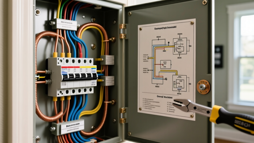
A theoretical wiring diagram for brake controller setups is useless if the physical execution fails due to poor termination. Follow this precise workflow to ensure a moisture-proof, vibration-resistant installation:
- Disconnect Power: Remove the negative battery terminal before routing any wires through the firewall or chassis.
- Firewall Routing: Use an existing rubber grommet. If piercing a new hole, install a nylon loom and a dedicated rubber firewall seal to prevent exhaust heat from melting the GXL insulation.
- Chassis Routing: Secure the 10 AWG blue (brake) and black (12V) wires using UV-resistant zip ties every 12 inches. Keep wiring at least 6 inches away from hot exhaust components and moving suspension parts.
- Circuit Protection: Install a 30A or 40A Maxi-fuse holder within 6 inches of the battery positive terminal. Do not rely solely on the controller's internal resettable breaker; a dead short in the engine bay requires immediate high-amperage interruption.
- Termination: Strip the wire using a precision gauge stripper. Crimp adhesive-lined heat shrink ring terminals using a ratcheting crimp tool (such as the Knipex 97 51 06). Apply heat until the adhesive sealant oozes from the edges, creating a watertight barrier against road salt.
Critical Failure Modes & Edge Case Troubleshooting
Even with a perfect wiring diagram for brake controller integration, environmental factors can introduce complex electrical faults. Below are the most common edge cases encountered by professional installers and how to resolve them:
The 'Hitch Ground' Fallacy: Never rely on the steel trailer hitch ball and coupler as your primary ground path for the trailer brakes. Rust, grease, and paint act as dielectrics, causing severe ground loops. This manifests as erratic brake pulsing or the controller displaying a 'C' (Connection) error code. Always run a dedicated 10 AWG white ground wire from Pin 3 of the 7-way directly to a bare, sanded spot on the vehicle's main chassis frame, and do the same on the trailer tongue.
Voltage Drop Diagnostics
If your trailer brakes feel weak despite the controller being set to maximum output, perform a loaded voltage drop test. Connect a digital multimeter in DC mode. Place the red probe on the battery positive post and the black probe on Pin 5 (Blue wire) at the rear 7-way connector. Have an assistant press the manual override lever on the brake controller to full power. A reading showing more than 0.5V of drop indicates undersized wiring, corroded inline fuse holders, or a failing crimp connection. Upgrading the blue output wire from 10 AWG to 8 AWG typically resolves this issue on extended-wheelbase trucks.
Backfeed and LED Interference
Modern trailers utilizing LED marker lights draw significantly less current than incandescent bulbs. Some older brake controllers misinterpret this low-draw state as a 'disconnected trailer' because they cannot detect the circuit continuity. If you encounter this, install a Curt 57003 LED Tow Bar Light Adapter or solder a 1/2-watt 600-ohm resistor in parallel with the running light circuit to simulate the electrical load of traditional bulbs, satisfying the controller's diagnostic ping.
Proper planning, adherence to RV Industry Association (RVIA) safety standards, and meticulous termination techniques will ensure your trailer braking system operates flawlessly for years to come, regardless of weather or terrain.