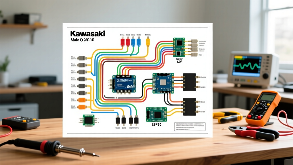

Decoding the Electrical Architecture of the KAF620
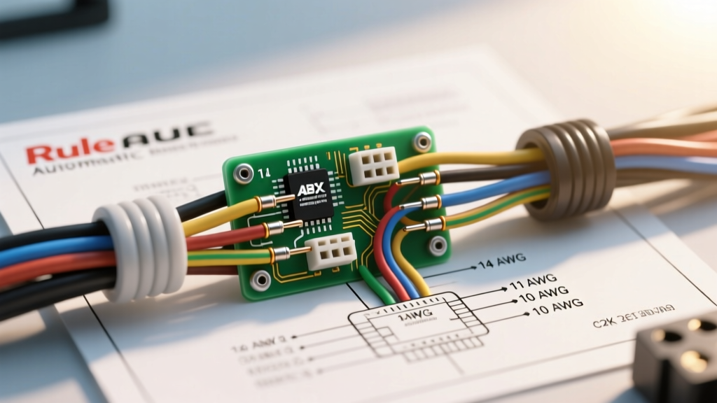
As we navigate through 2026, the Kawasaki Mule 3010 (KAF620 series) remains an indispensable workhorse on farms, ranches, and job sites. However, with these units now aging between 15 and 25 years, the primary electrical failure point is no longer just component burnout—it is severe wiring harness degradation, brittle loom, and corroded bulkhead connectors. Understanding the wiring diagram for Kawasaki Mule 3010 models is critical for accurate troubleshooting, whether you are dealing with a no-crank condition, a parasitic battery drain, or a complete stator failure.
The Mule 3010 utilizes a relatively straightforward 12V DC electrical system centered around a 3-phase AC stator, a combined regulator/rectifier (R/R), a capacitor discharge ignition (CDI) module, and a safety interlock system. Unlike modern EFI-driven UTVs with complex CAN-bus networks, the KAF620 relies on discrete, hardwired analog circuits. This makes it highly repairable in the field, provided you know how to read the schematic and use a digital multimeter (DMM) effectively.
Safety & Diagnostic Prep
Before probing any connectors, disconnect the negative battery terminal to prevent accidental shorts. When performing live voltage tests, ensure your DMM is set to the correct AC or DC voltage range. For deep-dive multimeter techniques, refer to the Fluke Corporation's Digital Multimeter Guide.
Kawasaki Standard Wire Color Code Matrix
Kawasaki adheres to a fairly consistent color-coding standard across its powersports lineup. While the exact wiring diagram for Kawasaki Mule 3010 sub-models (like the KAF620-E or the Trans 4x4 KAF620-H) may feature additional accessory wires, the core chassis and engine harness colors remain uniform. Always verify against the specific OEM schematic for your exact VIN, which can be cross-referenced via the Partzilla Kawasaki OEM Catalog.
| Wire Color | Primary Function | Circuit / Component |
|---|---|---|
| Red | Unswitched +12V DC | Battery positive, starter solenoid, main fuse |
| Black | Chassis Ground | Battery negative, CDI ground, lighting grounds |
| White / Yellow | 3-Phase AC Output | Stator to Regulator/Rectifier |
| Green | Sensor / Signal | Tachometer signal, neutral switch indicator |
| Brown | Switched +12V DC | Ignition switch output, tail lights, dash power |
| Gray | Instrumentation | Fuel sender unit signal to dash gauge |
Step-by-Step Diagnostic Workflows
When utilizing the wiring diagram for Kawasaki Mule 3010 troubleshooting, the most common complaints revolve around charging system failures and starting interlocks. Below are the exact diagnostic procedures used by master technicians.
1. Stator and Regulator/Rectifier Health Check
The KAF620 stator is a 3-phase alternator buried under the left-side engine cover. It generates raw AC voltage, which the R/R converts to regulated DC voltage to charge the 12V battery and run the DC headlights.
- Static Resistance Test (Engine Off): Disconnect the stator plug (three yellow/white wires). Set your DMM to Ohms (Ω). Measure resistance between each pair of the three stator wires. You should see roughly 0.5 to 2.0 ohms. Next, test for continuity between each stator wire and the engine block (ground). The meter should read 'OL' (Open Loop). Any continuity to ground indicates a burnt stator winding requiring replacement.
- Dynamic AC Voltage Test (Engine Running): Reconnect the stator, back-probe the three AC wires, and set the DMM to AC Voltage. Start the Mule. At idle (approx. 1,200 RPM), you should read 20V-30V AC between any two phases. Rev the engine to 3,000 RPM; the voltage should climb to 50V-70V AC. If one phase reads significantly lower, the stator is failing.
- Regulator/Rectifier DC Output: Set the DMM to DC Voltage. Measure directly at the battery terminals. At 2,000 RPM, the battery should read between 13.8V and 14.4V DC. If it reads above 15V, the R/R is overcharging (boiling the battery). If it reads below 13V, the R/R is failing to rectify the AC current.
2. Starter Solenoid and Safety Interlock Bypass
The Mule 3010 will not crank unless the transmission is in neutral and the PTO is disengaged. This is managed by the safety interlock module grounding the starter solenoid's trigger wire. If you turn the key and hear nothing (no click), the issue is often the neutral safety switch, not the starter.
- Locate the Solenoid: Found under the seat, near the battery. It has two large terminals (Battery +12V and Starter Motor) and two small spade terminals (Ignition trigger and Ground).
- The Bypass Test: With the key in the 'ON' position, use a heavy-gauge jumper wire to briefly bridge the two large terminals. If the starter motor spins, the starter and battery are healthy. The fault lies in the ignition switch, safety interlock module, or neutral switch wiring.
- Voltage Drop Test: If the solenoid clicks but the engine doesn't turn, perform a voltage drop test across the solenoid's large terminals while cranking. A drop greater than 0.2V indicates heavily corroded internal contacts inside the solenoid, necessitating a $35-$50 replacement.
Common Failure Modes & Edge Cases in Aging Harnesses
As these vehicles push past the two-decade mark, environmental factors take a severe toll on the wiring diagram for Kawasaki Mule 3010 implementations. Watch out for these specific edge cases:
Expert Insight: The KAF620-E and Trans models feature a complex multi-pin bulkhead connector located under the dashboard where the engine harness meets the chassis harness. Moisture ingress here causes 'green death' (copper oxidation). If your headlights flicker or the dash loses power over bumps, unplug this bulkhead, clean it with electrical contact cleaner, and apply dielectric grease. Do not simply replace the switch; trace the harness first.
- CDI Pickup Coil Degradation: The pulse coil (pickup coil) tells the CDI when to fire the ignition coil. Its resistance should be between 110 and 160 ohms at room temperature. As the epoxy encapsulating the coil breaks down from engine heat, resistance spikes, causing the Mule to die abruptly when hot and refuse to restart until it cools.
- Ignition Coil Secondary Breakdown: The ignition coil primary resistance should be 0.5–1.5 ohms, and secondary resistance 10k–15k ohms. A failing coil will show normal resistance when cold but arc internally under load when hot, resulting in a weak, yellow spark instead of a crisp blue one.
- The 'Click of Death': A rapid clicking from the solenoid usually means the battery has enough surface voltage to engage the relay, but lacks the Cold Cranking Amps (CCA) to hold it closed under the 80-amp load of the starter motor. Always load-test the battery before condemning the wiring.
Expert Upgrades for Longevity and Reliability
To modernize the KAF620 electrical system and prevent recurring failures, implement the following upgrades based on SAE J1128 Low Tension Primary Cable Standards for automotive wiring durability:
- Marine-Grade Ground Straps: The factory 14 AWG ground wires are prone to snapping due to engine vibration. Upgrade the main battery-to-frame and engine-to-frame grounds using 10 AWG marine-grade tinned copper wire with sealed heat-shrink ring terminals. Tinned copper resists the galvanic corrosion that destroys standard copper in wet, muddy environments.
- LED Lighting Relay Harness: The factory headlight switch and 18 AWG wiring were designed for 35W halogen bulbs. If you are adding LED light bars or upgrading to high-output LED headlights, do not route the load through the factory dash switch. Use the factory switch to trigger a 30A Bosch-style automotive relay wired directly to the battery via an inline 20A fuse.
- Heat-Shrink Solder Splices: Never use twist-on wire nuts or standard vinyl electrical tape for under-hood or under-seat repairs. The adhesive-lined, dual-wall heat shrink tubing with a solder core inside is the only acceptable method for splicing wires in the KAF620 engine bay, ensuring a waterproof, vibration-proof seal that matches OEM harness integrity.
By systematically applying these diagnostic steps and respecting the specific color codes and resistance values outlined in the Kawasaki Mule 3010 wiring diagram, you can reliably isolate and repair electrical faults, keeping this legendary utility vehicle running for decades to come.