
Understanding the Western Plow High-Current Architecture
When winter conditions demand relentless operation, your plow's hydraulic system is only as reliable as its electrical foundation. Interpreting a wiring diagram for a Western snow plow requires understanding the division between the high-amperage motor circuit and the low-amperage control logic. Modern Western systems, including the Ultramount, Pro-Plus, and MVP3 lines, draw anywhere from 150 to 250 amps under peak hydraulic load. This massive current draw means that standard automotive wiring practices are insufficient; heavy-duty routing, precise termination, and robust grounding are mandatory.
In 2026, the industry standard for Western plows relies heavily on the FleetFlex multiplex electrical system, which replaces older relay-based harnesses with solid-state control modules. However, the fundamental high-current path from the vehicle battery to the hydraulic pump motor remains largely unchanged. Mastering this specific circuit is the key to rapid field diagnostics and long-term reliability.
Core Components of the Motor Circuit
- Hydraulic Motor: Typically a Prestolite or Bosch 12V DC motor, rated for intermittent high-torque duty.
- Control Solenoid: A heavy-duty continuous or intermittent duty relay. The Trombetta 70-111224 (4-terminal) is the current standard for Western applications.
- Circuit Breaker: A 150A to 200A auto-reset thermal breaker (e.g., Littelfuse or Bussmann) mounted within 18 inches of the battery.
- Isolation (ISO) Module: The brain of the plow harness that separates the vehicle's lighting and control signals from the plow's high-draw components.
Decoding the Wiring Diagram for a Western Snow Plow
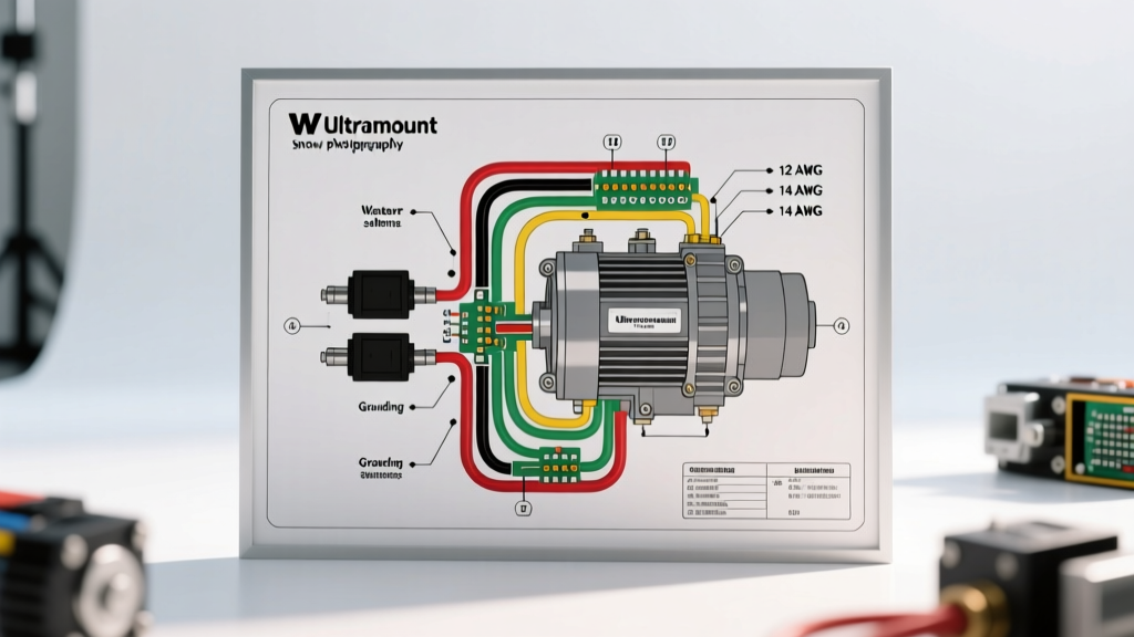
When you pull up the official schematic from Western Plows technical literature, the diagram will visually separate the 'Power' and 'Control' sides. The power side is drawn with thick lines, representing 2 AWG or 4 AWG cable, while the control side uses thin lines representing 14 AWG to 18 AWG wires.
Expert Grounding Rule: In DC snow plow circuits, the ground path is just as critical as the positive feed. Over 60% of 'weak motor' diagnostics in the field are actually caused by high resistance in the motor-to-chassis ground strap. Always treat the ground wire with the exact same gauge and termination standards as the positive feed.
Step-by-Step High-Amperage Routing
Follow this sequence to wire or verify the high-current motor path according to Western's engineering specifications:
- Battery to Circuit Breaker: Run 2 AWG pure copper welding cable from the positive battery terminal to the input stud of the 150A auto-reset breaker. Terminate with 3/8-inch copper lugs, crimped with a hydraulic tool, and seal with adhesive-lined dual-wall heat shrink.
- Circuit Breaker to Solenoid Input: Route 2 AWG cable from the breaker output to the primary high-current input stud on the Trombetta solenoid. Ensure this cable is loomed and secured away from exhaust manifolds and moving steering linkages.
- Solenoid Output to Motor: Connect 2 AWG (or 4 AWG if the run is under 4 feet) from the solenoid's output stud to the positive terminal on the hydraulic pump motor.
- Motor Ground to Chassis: Attach a 2 AWG ground cable from the motor's dedicated grounding bolt directly to a clean, bare-metal point on the vehicle frame. Use a wire brush to remove paint and rust, and coat the connection with dielectric grease after torquing.
- Control Circuit Activation: The ISO module sends a 12V signal via a 14 AWG wire to the solenoid's small activation terminal (usually marked 'S' or 'I'). The solenoid's ground terminal (marked 'G') must be tied to a clean chassis ground via a 14 AWG wire.
Wire Gauge, Amperage, and Component Specifications
Using undersized wire in a plow circuit will result in severe voltage drop, causing the motor to overheat and the solenoid contacts to pit and weld shut. Refer to the table below for 2026 component specifications and estimated replacement costs.
| Component / Wire Segment | Specification / Gauge | Amperage Rating | 2026 Est. Cost |
|---|---|---|---|
| Battery to Breaker Cable | 2 AWG Copper Welding Cable | 200A+ | $3.50 - $4.50 / ft |
| Auto-Reset Circuit Breaker | 150A or 200A Thermal (Littelfuse) | 150A - 200A | $28.00 - $42.00 |
| Control Solenoid (Trombetta) | 4-Terminal, 12V DC Intermittent | 150A Cont. / 400A Peak | $65.00 - $89.00 |
| Solenoid to Motor Cable | 2 AWG or 4 AWG Copper | 150A+ | $2.50 - $4.50 / ft |
| Control Signal Wire (ISO to Coil) | 14 AWG GXL or TXL Automotive | 15A | $0.60 / ft |
3-Terminal vs. 4-Terminal Solenoid Diagnostics
One of the most common points of confusion when reading a wiring diagram for a Western snow plow is identifying the solenoid type. Older setups utilized a 3-terminal solenoid, which relied on the metal mounting bracket to complete the coil's ground circuit. This design is highly prone to failure because rust and paint on the mounting surface create resistance, preventing the coil from fully engaging the plunger.
Modern Western diagrams specify a 4-terminal solenoid (like the Trombetta 70-111224). This unit features two large high-current studs and two small spade terminals for the coil positive and coil ground. If you are retrofitting an older plow, bypass the 3-terminal bracket ground and upgrade to a 4-terminal unit to eliminate ground-path voltage drop.
Voltage Drop Testing Protocol
Do not rely on simple continuity tests for high-current plow circuits; a wire with only two intact strands will show continuity on a multimeter but will fail catastrophically under a 150A load. Instead, perform a live voltage drop test:
- Set your digital multimeter to DC Volts.
- Connect the red probe to the battery positive terminal and the black probe to the motor positive terminal.
- Activate the plow motor (e.g., raise the blade to create a load).
- Read the voltage. A healthy high-current path will show a total voltage drop of less than 0.3V. If you read 0.5V or higher, you have severe resistance in a cable, lug, or the solenoid contacts themselves.
- Repeat the test on the ground side (Red probe on motor casing, black probe on battery negative). The drop should be less than 0.2V.
Common Failure Modes in the Field
Even with a perfect wiring diagram, environmental factors take a toll on snow plow electrical systems. Here are the most frequent failure modes encountered by fleet technicians:
- Solenoid Chatter or Clicking: If you hear a rapid clicking from the solenoid when pressing the control switch, the high-current contacts are likely pitted, or the 14 AWG control wire is suffering from voltage drop. The coil receives enough voltage to pull the plunger in, but the voltage sags under the coil's initial current spike, dropping the plunger back out.
- ISO Module Relay Click, No Motor Action: The control side is functioning (the ISO module is sending the signal), but the motor isn't spinning. This almost always points to a blown 150A main breaker, a severed 2 AWG cable, or a completely failed solenoid coil.
- Motor Runs Slow or Lacks Torque: Often misdiagnosed as a dying motor. Before replacing a $250 Prestolite motor, check the carbon brushes through the inspection band. If the brushes are worn past the 1/2-inch mark, or if the commutator is heavily scored, the motor is failing to draw the necessary amperage. Additionally, check for internal corrosion in the 2 AWG ground cable, which restricts current flow.
- FleetFlex Multiplex Communication Errors: On newer Western plows, if the cab controller displays a communication fault, the issue is rarely the motor itself. Check the 4-pin or 12-pin data connectors at the grill. Bent pins or moisture ingress in the communication CAN-bus lines will disable the entire system as a safety precaution.
Authoritative References and Further Reading
For exact pinouts, fleet-specific harness routing, and warranty-compliant repair procedures, always consult the manufacturer's latest documentation and industry-standard component datasheets:
- Western Plows Official Support and Literature Library - Access current mechanic's guides, electrical schematics, and FleetFlex troubleshooting flowcharts.
- Trombetta Corporation Engineering Datasheets - Review the exact pull-in and hold-in amperage specifications for heavy-duty DC solenoids used in hydraulic systems.
- Littelfuse Automotive Circuit Protection - Technical data on high-amperage thermal and magnetic circuit breakers designed for severe-duty winter equipment.